

214
5 Flux-Charge Analysis Method of Memristor Circuits
e(t)
R 1
C 1
f (ϕ M )
R 2
C 2
−
+
ϕ e (t; t 0 )
R 1
ϕ 1 (t; t 0 )
ϕ M0
f (ϕ M )
f (ϕ M0 )
(a)
(b)
R 2
ϕ 2 (t; t 0 )
q2(t; t0)
−
+
A
C
q1(t; t0)
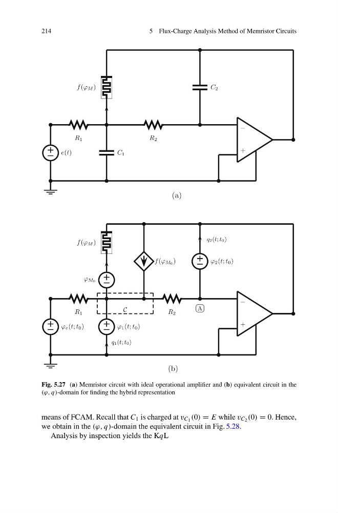
Fig. 5.27 (a) Memristor circuit with ideal operational amplifier and (b) equivalent circuit in the
(ϕ, q)-domain for finding the hybrid representation
means of FCAM. Recall that C 1 is charged at v C 1 (0) = E while v C 2 (0) = 0. Hence,
we obtain in the (ϕ, q)-domain the equivalent circuit in Fig. 5.28.
Analysis by inspection yields the KqL
5 Flux-Charge Analysis Method of Memristor Circuits
e(t)
R 1
C 1
f (ϕ M )
R 2
C 2
−
+
ϕ e (t; t 0 )
R 1
ϕ 1 (t; t 0 )
ϕ M0
f (ϕ M )
f (ϕ M0 )
(a)
(b)
R 2
ϕ 2 (t; t 0 )
q2(t; t0)
−
+
A
C
q1(t; t0)
Fig. 5.27 (a) Memristor circuit with ideal operational amplifier and (b) equivalent circuit in the
(ϕ, q)-domain for finding the hybrid representation
means of FCAM. Recall that C 1 is charged at v C 1 (0) = E while v C 2 (0) = 0. Hence,
we obtain in the (ϕ, q)-domain the equivalent circuit in Fig. 5.28.
Analysis by inspection yields the KqL