

5.7 Analogy Between a Nonlinear RLC Circuit and a Memristor Circuit
193
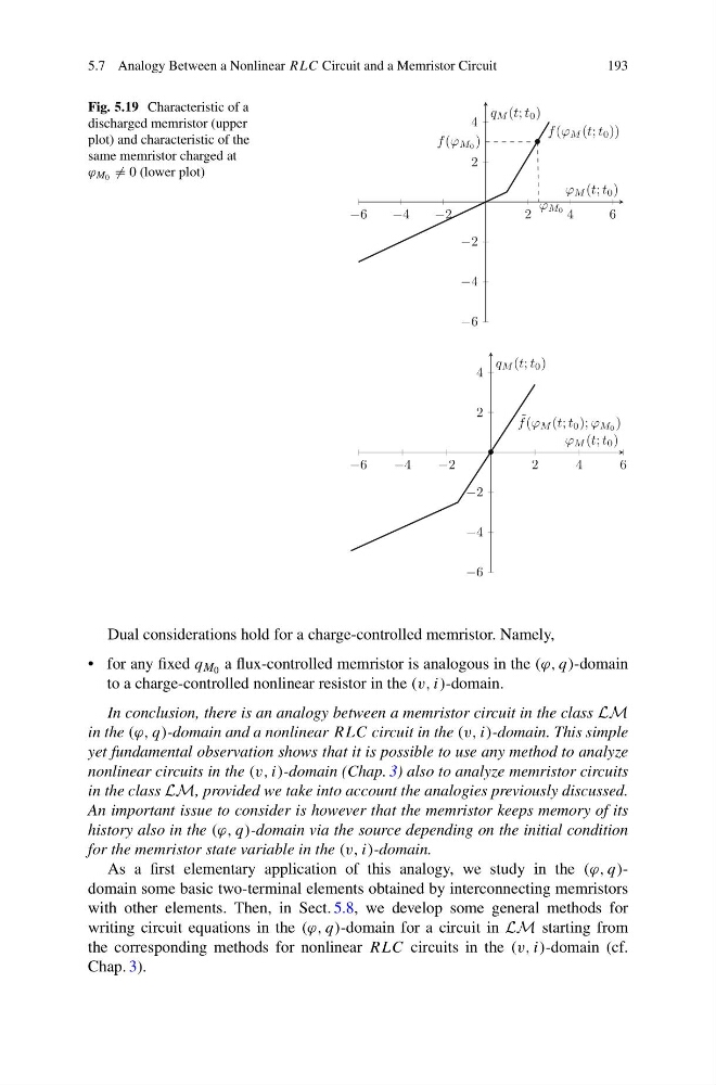
Fig. 5.19 Characteristic of a
discharged memristor (upper
plot) and characteristic of the
same memristor charged at
ϕ M 0 = 0 (lower plot)
−6
−4
−2
2
4
6
−6
−4
−2
2
4
ϕ M0
f (ϕ M0 )
•
f (ϕ M (t; t 0 ))
ϕ M (t; t 0 )
q M (t; t 0 )
−6
−4
−2
2
4
6
−6
−4
−2
2
4
•
˜
f (ϕ M (t; t 0 ); ϕ M0 )
ϕ M (t; t 0 )
q M (t; t 0 )
Dual considerations hold for a charge-controlled memristor. Namely,
• for any fixed q M 0 a flux-controlled memristor is analogous in the (ϕ, q)-domain
to a charge-controlled nonlinear resistor in the (v, i)-domain.
In conclusion, there is an analogy between a memristor circuit in the class LM
in the (ϕ, q)-domain and a nonlinear RLC circuit in the (v, i)-domain. This simple
yet fundamental observation shows that it is possible to use any method to analyze
nonlinear circuits in the (v, i)-domain (Chap. 3) also to analyze memristor circuits
in the class LM, provided we take into account the analogies previously discussed.
An important issue to consider is however that the memristor keeps memory of its
history also in the (ϕ, q)-domain via the source depending on the initial condition
for the memristor state variable in the (v, i)-domain.
As a first elementary application of this analogy, we study in the (ϕ, q)domain some basic two-terminal elements obtained by interconnecting memristors
with other elements. Then, in Sect. 5.8, we develop some general methods for
writing circuit equations in the (ϕ, q)-domain for a circuit in LM starting from
the corresponding methods for nonlinear RLC circuits in the (v, i)-domain (cf.
Chap. 3).
193
Fig. 5.19 Characteristic of a
discharged memristor (upper
plot) and characteristic of the
same memristor charged at
ϕ M 0 = 0 (lower plot)
−6
−4
−2
2
4
6
−6
−4
−2
2
4
ϕ M0
f (ϕ M0 )
•
f (ϕ M (t; t 0 ))
ϕ M (t; t 0 )
q M (t; t 0 )
−6
−4
−2
2
4
6
−6
−4
−2
2
4
•
˜
f (ϕ M (t; t 0 ); ϕ M0 )
ϕ M (t; t 0 )
q M (t; t 0 )
Dual considerations hold for a charge-controlled memristor. Namely,
• for any fixed q M 0 a flux-controlled memristor is analogous in the (ϕ, q)-domain
to a charge-controlled nonlinear resistor in the (v, i)-domain.
In conclusion, there is an analogy between a memristor circuit in the class LM
in the (ϕ, q)-domain and a nonlinear RLC circuit in the (v, i)-domain. This simple
yet fundamental observation shows that it is possible to use any method to analyze
nonlinear circuits in the (v, i)-domain (Chap. 3) also to analyze memristor circuits
in the class LM, provided we take into account the analogies previously discussed.
An important issue to consider is however that the memristor keeps memory of its
history also in the (ϕ, q)-domain via the source depending on the initial condition
for the memristor state variable in the (v, i)-domain.
As a first elementary application of this analogy, we study in the (ϕ, q)domain some basic two-terminal elements obtained by interconnecting memristors
with other elements. Then, in Sect. 5.8, we develop some general methods for
writing circuit equations in the (ϕ, q)-domain for a circuit in LM starting from
the corresponding methods for nonlinear RLC circuits in the (v, i)-domain (cf.
Chap. 3).