

190
5 Flux-Charge Analysis Method of Memristor Circuits
L 2
L 1
M
−
+
v 1
−
+
v 2
i 1
i 2
(a)
L 2
L 1
L 1 i 10
M i 20
L 2 i 20
M i 10
M
−
+
ϕ 1 (t; t 0 )
−
+
ϕ 2 (t; t 0 )
q 1 (t; t 0 )
q 2 (t; t 0 )
(b)
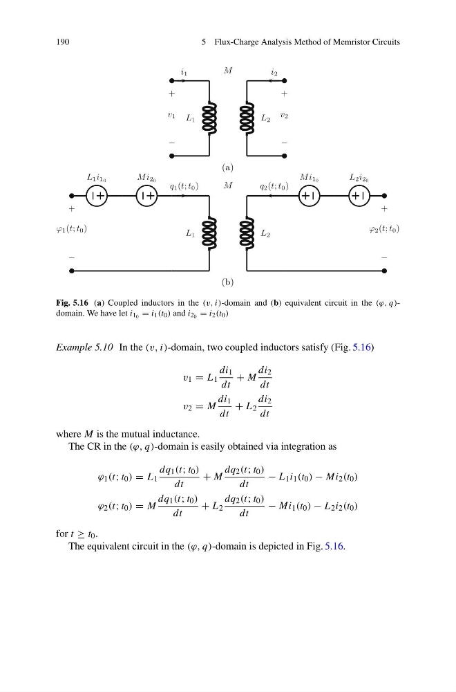
Fig. 5.16 (a) Coupled inductors in the (v, i)-domain and (b) equivalent circuit in the (ϕ, q)domain. We have let i 1 0 = i 1 (t 0 ) and i 2 0 = i 2 (t 0 )
Example 5.10 In the (v, i)-domain, two coupled inductors satisfy (Fig. 5.16)
v 1 = L 1
di 1
dt
+ M
di 2
dt
v 2 = M
di 1
dt
+ L 2
di 2
dt
where M is the mutual inductance.
The CR in the (ϕ, q)-domain is easily obtained via integration as
ϕ 1 (t; t 0 ) = L 1
dq 1 (t; t 0 )
dt
+ M
dq 2 (t; t 0 )
dt
− L 1 i 1 (t 0 ) − Mi 2 (t 0 )
ϕ 2 (t; t 0 ) = M
dq 1 (t; t 0 )
dt
+ L 2
dq 2 (t; t 0 )
dt
− Mi 1 (t 0 ) − L 2 i 2 (t 0 )
for t ≥ t 0 .
The equivalent circuit in the (ϕ, q)-domain is depicted in Fig. 5.16.
5 Flux-Charge Analysis Method of Memristor Circuits
L 2
L 1
M
−
+
v 1
−
+
v 2
i 1
i 2
(a)
L 2
L 1
L 1 i 10
M i 20
L 2 i 20
M i 10
M
−
+
ϕ 1 (t; t 0 )
−
+
ϕ 2 (t; t 0 )
q 1 (t; t 0 )
q 2 (t; t 0 )
(b)
Fig. 5.16 (a) Coupled inductors in the (v, i)-domain and (b) equivalent circuit in the (ϕ, q)domain. We have let i 1 0 = i 1 (t 0 ) and i 2 0 = i 2 (t 0 )
Example 5.10 In the (v, i)-domain, two coupled inductors satisfy (Fig. 5.16)
v 1 = L 1
di 1
dt
+ M
di 2
dt
v 2 = M
di 1
dt
+ L 2
di 2
dt
where M is the mutual inductance.
The CR in the (ϕ, q)-domain is easily obtained via integration as
ϕ 1 (t; t 0 ) = L 1
dq 1 (t; t 0 )
dt
+ M
dq 2 (t; t 0 )
dt
− L 1 i 1 (t 0 ) − Mi 2 (t 0 )
ϕ 2 (t; t 0 ) = M
dq 1 (t; t 0 )
dt
+ L 2
dq 2 (t; t 0 )
dt
− Mi 1 (t 0 ) − L 2 i 2 (t 0 )
for t ≥ t 0 .
The equivalent circuit in the (ϕ, q)-domain is depicted in Fig. 5.16.