

144
4 Nonlinear Dynamics and Bifurcations in Autonomous RLC Circuits
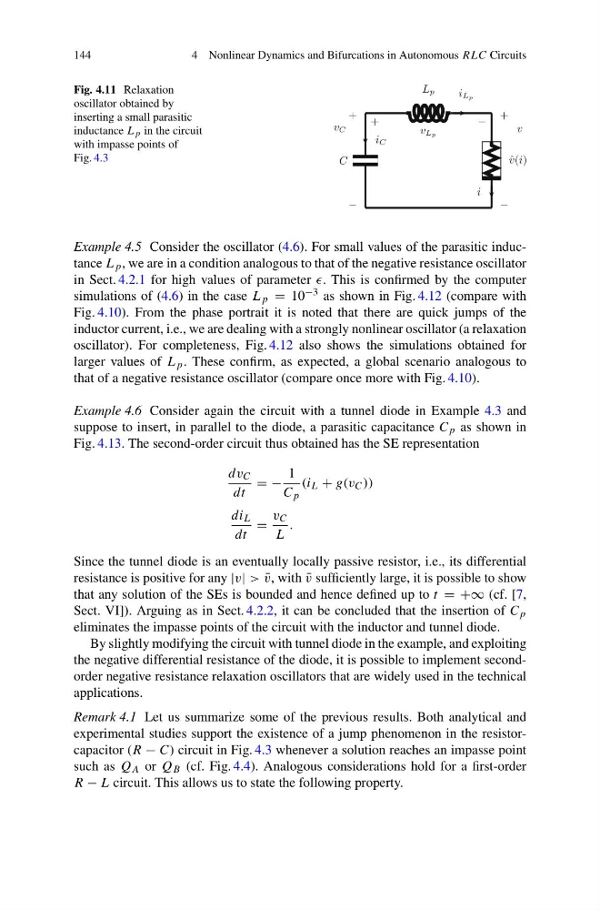
Fig. 4.11 Relaxation
oscillator obtained by
inserting a small parasitic
inductance L p in the circuit
with impasse points of
Fig. 4.3
Example 4.5 Consider the oscillator (4.6). For small values of the parasitic inductance L p , we are in a condition analogous to that of the negative resistance oscillator
in Sect. 4.2.1 for high values of parameter . This is confirmed by the computer
simulations of (4.6) in the case L p = 10 −3 as shown in Fig. 4.12 (compare with
Fig. 4.10). From the phase portrait it is noted that there are quick jumps of the
inductor current, i.e., we are dealing with a strongly nonlinear oscillator (a relaxation
oscillator). For completeness, Fig. 4.12 also shows the simulations obtained for
larger values of L p . These confirm, as expected, a global scenario analogous to
that of a negative resistance oscillator (compare once more with Fig. 4.10).
Example 4.6 Consider again the circuit with a tunnel diode in Example 4.3 and
suppose to insert, in parallel to the diode, a parasitic capacitance C p as shown in
Fig. 4.13. The second-order circuit thus obtained has the SE representation
dv C
dt
= −
1
C p
(i L + g(v C ))
di L
dt
=
v C
L
.
Since the tunnel diode is an eventually locally passive resistor, i.e., its differential
resistance is positive for any |v| > ¯
v, with ¯
v sufficiently large, it is possible to show
that any solution of the SEs is bounded and hence defined up to t = +∞ (cf. [7,
Sect. VI]). Arguing as in Sect. 4.2.2, it can be concluded that the insertion of C p
eliminates the impasse points of the circuit with the inductor and tunnel diode.
By slightly modifying the circuit with tunnel diode in the example, and exploiting
the negative differential resistance of the diode, it is possible to implement secondorder negative resistance relaxation oscillators that are widely used in the technical
applications.
Remark 4.1 Let us summarize some of the previous results. Both analytical and
experimental studies support the existence of a jump phenomenon in the resistorcapacitor (R − C) circuit in Fig. 4.3 whenever a solution reaches an impasse point
such as Q A or Q B (cf. Fig. 4.4). Analogous considerations hold for a first-order
R − L circuit. This allows us to state the following property.
4 Nonlinear Dynamics and Bifurcations in Autonomous RLC Circuits
Fig. 4.11 Relaxation
oscillator obtained by
inserting a small parasitic
inductance L p in the circuit
with impasse points of
Fig. 4.3
Example 4.5 Consider the oscillator (4.6). For small values of the parasitic inductance L p , we are in a condition analogous to that of the negative resistance oscillator
in Sect. 4.2.1 for high values of parameter . This is confirmed by the computer
simulations of (4.6) in the case L p = 10 −3 as shown in Fig. 4.12 (compare with
Fig. 4.10). From the phase portrait it is noted that there are quick jumps of the
inductor current, i.e., we are dealing with a strongly nonlinear oscillator (a relaxation
oscillator). For completeness, Fig. 4.12 also shows the simulations obtained for
larger values of L p . These confirm, as expected, a global scenario analogous to
that of a negative resistance oscillator (compare once more with Fig. 4.10).
Example 4.6 Consider again the circuit with a tunnel diode in Example 4.3 and
suppose to insert, in parallel to the diode, a parasitic capacitance C p as shown in
Fig. 4.13. The second-order circuit thus obtained has the SE representation
dv C
dt
= −
1
C p
(i L + g(v C ))
di L
dt
=
v C
L
.
Since the tunnel diode is an eventually locally passive resistor, i.e., its differential
resistance is positive for any |v| > ¯
v, with ¯
v sufficiently large, it is possible to show
that any solution of the SEs is bounded and hence defined up to t = +∞ (cf. [7,
Sect. VI]). Arguing as in Sect. 4.2.2, it can be concluded that the insertion of C p
eliminates the impasse points of the circuit with the inductor and tunnel diode.
By slightly modifying the circuit with tunnel diode in the example, and exploiting
the negative differential resistance of the diode, it is possible to implement secondorder negative resistance relaxation oscillators that are widely used in the technical
applications.
Remark 4.1 Let us summarize some of the previous results. Both analytical and
experimental studies support the existence of a jump phenomenon in the resistorcapacitor (R − C) circuit in Fig. 4.3 whenever a solution reaches an impasse point
such as Q A or Q B (cf. Fig. 4.4). Analogous considerations hold for a first-order
R − L circuit. This allows us to state the following property.