

138
4 Nonlinear Dynamics and Bifurcations in Autonomous RLC Circuits
E
R
+
−
v
i = g(v)
(a)
•
¯
v 1
•
¯
v 2
•
¯
v 3
g(v)
v
i
(b)
E
C p
R
+
−
v
i = g(v) +
−
v C
iC
(c)
•
¯
v C1 = ¯
v 1
•
¯
v C2 = ¯
v 2
•
¯
v C3 = ¯
v 3
v C
dvC
dt
(d)
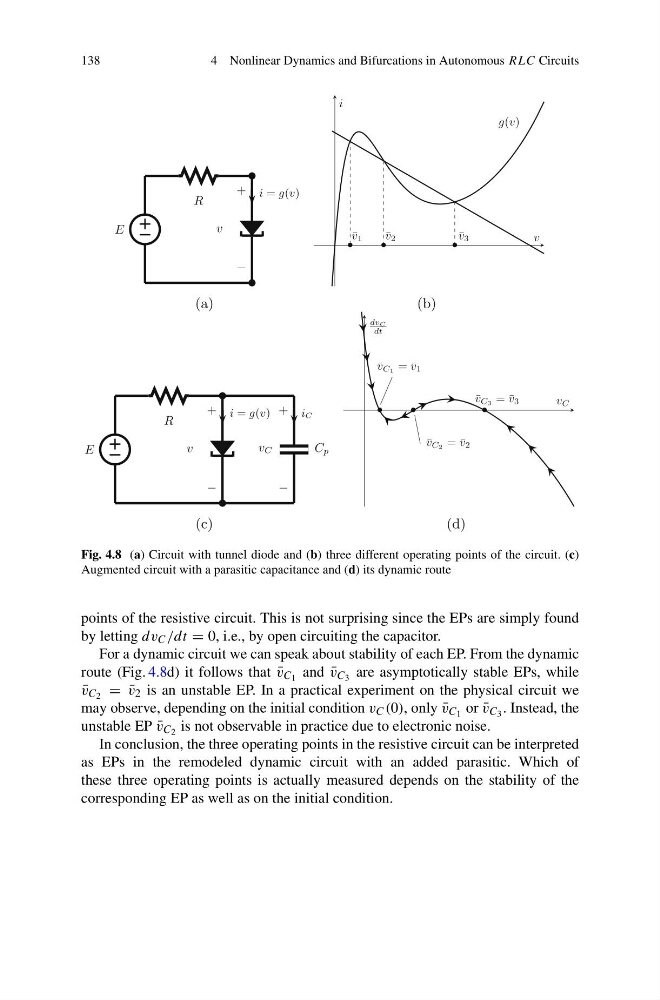
Fig. 4.8 (a) Circuit with tunnel diode and (b) three different operating points of the circuit. (c)
Augmented circuit with a parasitic capacitance and (d) its dynamic route
points of the resistive circuit. This is not surprising since the EPs are simply found
by letting dv C /dt = 0, i.e., by open circuiting the capacitor.
For a dynamic circuit we can speak about stability of each EP. From the dynamic
route (Fig. 4.8d) it follows that ¯
v C 1 and ¯
v C 3 are asymptotically stable EPs, while
¯
v C 2 = ¯
v 2 is an unstable EP. In a practical experiment on the physical circuit we
may observe, depending on the initial condition v C (0), only ¯
v C 1 or ¯
v C 3 . Instead, the
unstable EP ¯
v C 2 is not observable in practice due to electronic noise.
In conclusion, the three operating points in the resistive circuit can be interpreted
as EPs in the remodeled dynamic circuit with an added parasitic. Which of
these three operating points is actually measured depends on the stability of the
corresponding EP as well as on the initial condition.
4 Nonlinear Dynamics and Bifurcations in Autonomous RLC Circuits
E
R
+
−
v
i = g(v)
(a)
•
¯
v 1
•
¯
v 2
•
¯
v 3
g(v)
v
i
(b)
E
C p
R
+
−
v
i = g(v) +
−
v C
iC
(c)
•
¯
v C1 = ¯
v 1
•
¯
v C2 = ¯
v 2
•
¯
v C3 = ¯
v 3
v C
dvC
dt
(d)
Fig. 4.8 (a) Circuit with tunnel diode and (b) three different operating points of the circuit. (c)
Augmented circuit with a parasitic capacitance and (d) its dynamic route
points of the resistive circuit. This is not surprising since the EPs are simply found
by letting dv C /dt = 0, i.e., by open circuiting the capacitor.
For a dynamic circuit we can speak about stability of each EP. From the dynamic
route (Fig. 4.8d) it follows that ¯
v C 1 and ¯
v C 3 are asymptotically stable EPs, while
¯
v C 2 = ¯
v 2 is an unstable EP. In a practical experiment on the physical circuit we
may observe, depending on the initial condition v C (0), only ¯
v C 1 or ¯
v C 3 . Instead, the
unstable EP ¯
v C 2 is not observable in practice due to electronic noise.
In conclusion, the three operating points in the resistive circuit can be interpreted
as EPs in the remodeled dynamic circuit with an added parasitic. Which of
these three operating points is actually measured depends on the stability of the
corresponding EP as well as on the initial condition.