

122
3 RLC Networks Equations and Analysis Methods
+
−
v 1
i1
N
vC 1
iC 1
+
−
+
−
v2
i2
vL 2
iL 2
−
+
(a)
v 1
i 2
+
−
v 1
i1
N
+
−
v2
i2
(b)
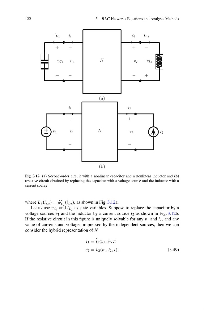
Fig. 3.12 (a) Second-order circuit with a nonlinear capacitor and a nonlinear inductor and (b)
resistive circuit obtained by replacing the capacitor with a voltage source and the inductor with a
current source
where L 2 (i L 2 ) = ˆ
ϕ
L 2
(i L 2 ), as shown in Fig. 3.12a.
Let us use v C 1 and i L 2 as state variables. Suppose to replace the capacitor by a
voltage sources v 1 and the inductor by a current source i 2 as shown in Fig. 3.12b.
If the resistive circuit in this figure is uniquely solvable for any v 1 and i 2 , and any
value of currents and voltages impressed by the independent sources, then we can
consider the hybrid representation of N
i 1 = ˆ
i 1 (v 1 , i 2 , t)
v 2 = ˆ
v 2 (v 1 , i 2 , t).
(3.49)
3 RLC Networks Equations and Analysis Methods
+
−
v 1
i1
N
vC 1
iC 1
+
−
+
−
v2
i2
vL 2
iL 2
−
+
(a)
v 1
i 2
+
−
v 1
i1
N
+
−
v2
i2
(b)
Fig. 3.12 (a) Second-order circuit with a nonlinear capacitor and a nonlinear inductor and (b)
resistive circuit obtained by replacing the capacitor with a voltage source and the inductor with a
current source
where L 2 (i L 2 ) = ˆ
ϕ
L 2
(i L 2 ), as shown in Fig. 3.12a.
Let us use v C 1 and i L 2 as state variables. Suppose to replace the capacitor by a
voltage sources v 1 and the inductor by a current source i 2 as shown in Fig. 3.12b.
If the resistive circuit in this figure is uniquely solvable for any v 1 and i 2 , and any
value of currents and voltages impressed by the independent sources, then we can
consider the hybrid representation of N
i 1 = ˆ
i 1 (v 1 , i 2 , t)
v 2 = ˆ
v 2 (v 1 , i 2 , t).
(3.49)