

120
3 RLC Networks Equations and Analysis Methods
C
+
−
v
i
N
vC
iC
+
−
v
+
−
v
i
N
)
b
(
)
a
(
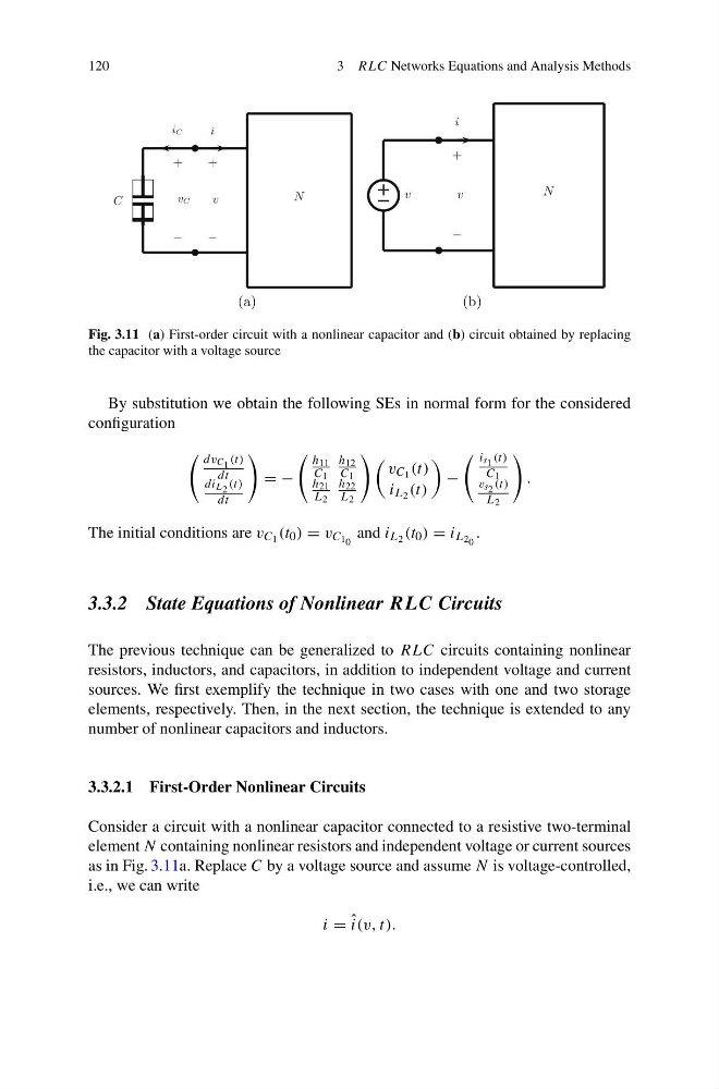
Fig. 3.11 (a) First-order circuit with a nonlinear capacitor and (b) circuit obtained by replacing
the capacitor with a voltage source
By substitution we obtain the following SEs in normal form for the considered
configuration
dv C 1 (t)
dt
di L 2 (t)
dt
= −
h 11
C 1
h 12
C 1
h 21
L 2
h 22
L 2
v C 1 (t)
i L 2 (t)
−
i s 1 (t)
C 1
v s 2 (t)
L 2
.
The initial conditions are v C 1 (t 0 ) = v C 1 0 and i L 2 (t 0 ) = i L 2 0 .
3.3.2 State Equations of Nonlinear RLC Circuits
The previous technique can be generalized to RLC circuits containing nonlinear
resistors, inductors, and capacitors, in addition to independent voltage and current
sources. We first exemplify the technique in two cases with one and two storage
elements, respectively. Then, in the next section, the technique is extended to any
number of nonlinear capacitors and inductors.
3.3.2.1 First-Order Nonlinear Circuits
Consider a circuit with a nonlinear capacitor connected to a resistive two-terminal
element N containing nonlinear resistors and independent voltage or current sources
as in Fig. 3.11a. Replace C by a voltage source and assume N is voltage-controlled,
i.e., we can write
i = ˆ
i(v, t).
3 RLC Networks Equations and Analysis Methods
C
+
−
v
i
N
vC
iC
+
−
v
+
−
v
i
N
)
b
(
)
a
(
Fig. 3.11 (a) First-order circuit with a nonlinear capacitor and (b) circuit obtained by replacing
the capacitor with a voltage source
By substitution we obtain the following SEs in normal form for the considered
configuration
dv C 1 (t)
dt
di L 2 (t)
dt
= −
h 11
C 1
h 12
C 1
h 21
L 2
h 22
L 2
v C 1 (t)
i L 2 (t)
−
i s 1 (t)
C 1
v s 2 (t)
L 2
.
The initial conditions are v C 1 (t 0 ) = v C 1 0 and i L 2 (t 0 ) = i L 2 0 .
3.3.2 State Equations of Nonlinear RLC Circuits
The previous technique can be generalized to RLC circuits containing nonlinear
resistors, inductors, and capacitors, in addition to independent voltage and current
sources. We first exemplify the technique in two cases with one and two storage
elements, respectively. Then, in the next section, the technique is extended to any
number of nonlinear capacitors and inductors.
3.3.2.1 First-Order Nonlinear Circuits
Consider a circuit with a nonlinear capacitor connected to a resistive two-terminal
element N containing nonlinear resistors and independent voltage or current sources
as in Fig. 3.11a. Replace C by a voltage source and assume N is voltage-controlled,
i.e., we can write
i = ˆ
i(v, t).