

116
3 RLC Networks Equations and Analysis Methods
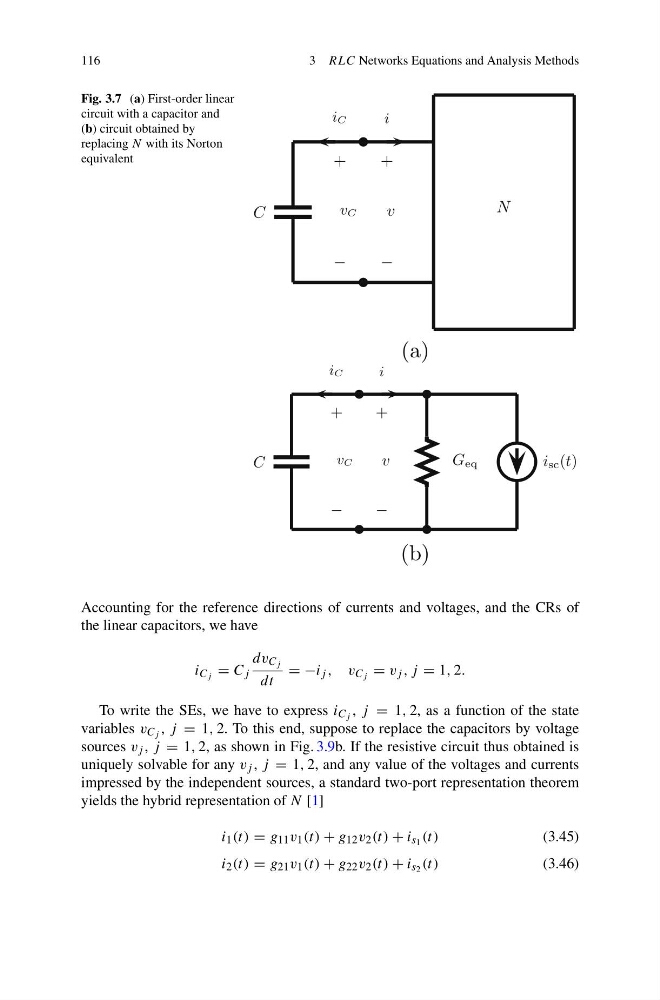
Fig. 3.7 (a) First-order linear
circuit with a capacitor and
(b) circuit obtained by
replacing N with its Norton
equivalent
C
+
−
v
i
N
v C
i C
+
−
(a)
C
+
−
v
i
v C
i C
+
−
G eq
i sc (t)
(b)
Accounting for the reference directions of currents and voltages, and the CRs of
the linear capacitors, we have
i C j = C j
dv C j
dt
= −i j , v C j = v j , j = 1, 2.
To write the SEs, we have to express i C j , j = 1, 2, as a function of the state
variables v C j , j = 1, 2. To this end, suppose to replace the capacitors by voltage
sources v j , j = 1, 2, as shown in Fig. 3.9b. If the resistive circuit thus obtained is
uniquely solvable for any v j , j = 1, 2, and any value of the voltages and currents
impressed by the independent sources, a standard two-port representation theorem
yields the hybrid representation of N [1]
i 1 (t) = g 11 v 1 (t) + g 12 v 2 (t) + i s 1 (t)
(3.45)
i 2 (t) = g 21 v 1 (t) + g 22 v 2 (t) + i s 2 (t)
(3.46)
3 RLC Networks Equations and Analysis Methods
Fig. 3.7 (a) First-order linear
circuit with a capacitor and
(b) circuit obtained by
replacing N with its Norton
equivalent
C
+
−
v
i
N
v C
i C
+
−
(a)
C
+
−
v
i
v C
i C
+
−
G eq
i sc (t)
(b)
Accounting for the reference directions of currents and voltages, and the CRs of
the linear capacitors, we have
i C j = C j
dv C j
dt
= −i j , v C j = v j , j = 1, 2.
To write the SEs, we have to express i C j , j = 1, 2, as a function of the state
variables v C j , j = 1, 2. To this end, suppose to replace the capacitors by voltage
sources v j , j = 1, 2, as shown in Fig. 3.9b. If the resistive circuit thus obtained is
uniquely solvable for any v j , j = 1, 2, and any value of the voltages and currents
impressed by the independent sources, a standard two-port representation theorem
yields the hybrid representation of N [1]
i 1 (t) = g 11 v 1 (t) + g 12 v 2 (t) + i s 1 (t)
(3.45)
i 2 (t) = g 21 v 1 (t) + g 22 v 2 (t) + i s 2 (t)
(3.46)