

4.2 Representation of Planes and Directions of Known
Miller Indices in Cubic Unit Cell
(a) Representation of Planes
Planes of known Miller indices can be represented in a unit cell by using the
following procedure:
(i) Take the reciprocal of given Miller indices. They will represent the intercepts
in terms of axial units.
(ii) If a Miller index is negative, shift the origin by moving it in the positive
direction along that axis.
(iii) Mark the length of the intercepts on the respective coordinate axes, each one
starting from the origin. Join their end points; the resulting sketch will
represent the required (hkl) plane.
(b) Representation of Directions
Directions of known Miller indices can be represented in a unit cell by using the
following procedure:
(i) Divide the given Miller indices by a number such that the resulting indices
become 1; they represent the coordinates of the lattice site nearest to the
origin in the given direction and lie within the unit cell.
(ii) If a lattice site nearest to the origin contains fractional coordinates, remove
the fraction by multiplying them with suitable number.
(iii) Mark the length of the position vector along the respective coordinate axes
without disconnection. Join the origin with the end point to get the required
[hkl] direction.
Solved Examples
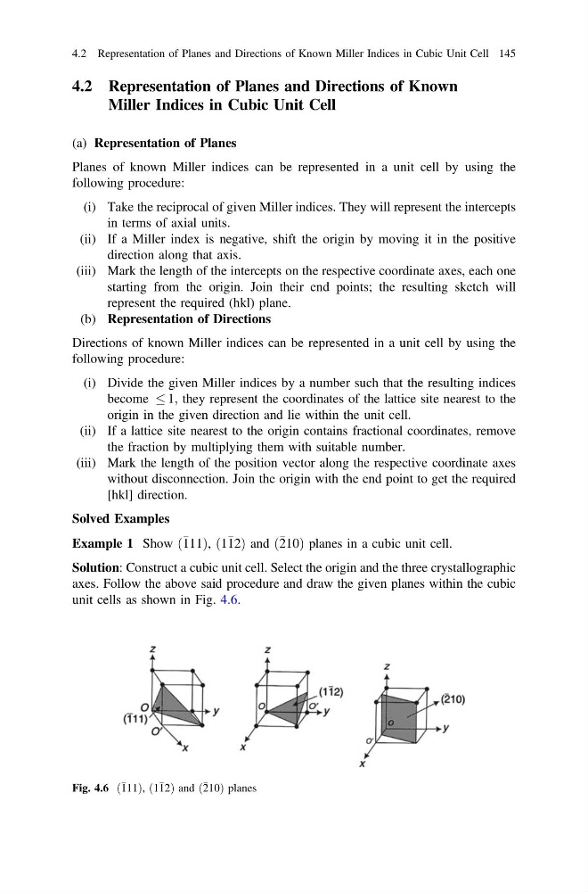
Example 1 Show 111
ð
Þ, 1 12
ð
Þ and 210
ð
Þ planes in a cubic unit cell.
Solution: Construct a cubic unit cell. Select the origin and the three crystallographic
axes. Follow the above said procedure and draw the given planes within the cubic
unit cells as shown in Fig. 4.6.
Fig. 4.6 111
ð Þ, 1 12
ð
Þ and 210
ð Þ planes
4.2 Representation of Planes and Directions of Known Miller Indices in Cubic Unit Cell 145
Miller Indices in Cubic Unit Cell
(a) Representation of Planes
Planes of known Miller indices can be represented in a unit cell by using the
following procedure:
(i) Take the reciprocal of given Miller indices. They will represent the intercepts
in terms of axial units.
(ii) If a Miller index is negative, shift the origin by moving it in the positive
direction along that axis.
(iii) Mark the length of the intercepts on the respective coordinate axes, each one
starting from the origin. Join their end points; the resulting sketch will
represent the required (hkl) plane.
(b) Representation of Directions
Directions of known Miller indices can be represented in a unit cell by using the
following procedure:
(i) Divide the given Miller indices by a number such that the resulting indices
become 1; they represent the coordinates of the lattice site nearest to the
origin in the given direction and lie within the unit cell.
(ii) If a lattice site nearest to the origin contains fractional coordinates, remove
the fraction by multiplying them with suitable number.
(iii) Mark the length of the position vector along the respective coordinate axes
without disconnection. Join the origin with the end point to get the required
[hkl] direction.
Solved Examples
Example 1 Show 111
ð
Þ, 1 12
ð
Þ and 210
ð
Þ planes in a cubic unit cell.
Solution: Construct a cubic unit cell. Select the origin and the three crystallographic
axes. Follow the above said procedure and draw the given planes within the cubic
unit cells as shown in Fig. 4.6.
Fig. 4.6 111
ð Þ, 1 12
ð
Þ and 210
ð Þ planes
4.2 Representation of Planes and Directions of Known Miller Indices in Cubic Unit Cell 145