

6.7 Going Further: Analytical Modelling of Vibroacoustic Coupling in Ducts
329
L =
⎛
⎜
⎜
⎜
⎜
⎜
⎜
⎝
a 2 ∂ 2
∂z 2 +
1 − ν
2
∂ 2
∂θ 2
1 + ν
2
a
∂ 2
∂z∂θ
νa
∂
∂z
1 + ν
2
a
∂ 2
∂z∂θ
∂ 2
∂θ 2 +
1 − ν
2
a 2 ∂ 2
∂x 2
∂
∂θ
−νa
∂
∂z
−
∂
∂θ
−1 − η
a 2 ∂ 2
∂z 2 +
∂ 2
∂θ 2
⎞
⎟
⎟
⎟
⎟
⎟
⎟
⎠
,
(6.42)
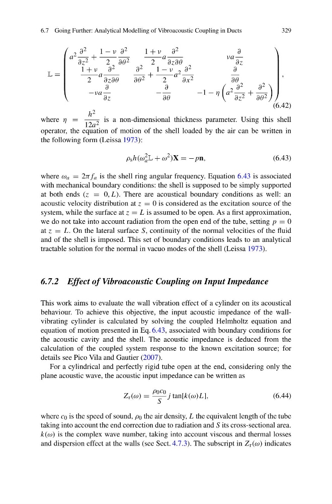
where η =
h 2
12a 2 is a non-dimensional thickness parameter. Using this shell
operator, the equation of motion of the shell loaded by the air can be written in
the following form (Leissa 1973):
ρ s h(ω
2
a L + ω
2 )X = −pn,
(6.43)
where ω a = 2πf a is the shell ring angular frequency. Equation 6.43 is associated
with mechanical boundary conditions: the shell is supposed to be simply supported
at both ends (z = 0, L). There are acoustical boundary conditions as well: an
acoustic velocity distribution at z = 0 is considered as the excitation source of the
system, while the surface at z = L is assumed to be open. As a first approximation,
we do not take into account radiation from the open end of the tube, setting p = 0
at z = L. On the lateral surface S, continuity of the normal velocities of the fluid
and of the shell is imposed. This set of boundary conditions leads to an analytical
tractable solution for the normal in vacuo modes of the shell (Leissa 1973).
6.7.2 Effect of Vibroacoustic Coupling on Input Impedance
This work aims to evaluate the wall vibration effect of a cylinder on its acoustical
behaviour. To achieve this objective, the input acoustic impedance of the wallvibrating cylinder is calculated by solving the coupled Helmholtz equation and
equation of motion presented in Eq. 6.43, associated with boundary conditions for
the acoustic cavity and the shell. The acoustic impedance is deduced from the
calculation of the coupled system response to the known excitation source; for
details see Pico Vila and Gautier (2007).
For a cylindrical and perfectly rigid tube open at the end, considering only the
plane acoustic wave, the acoustic input impedance can be written as
Z r (ω) =
ρ 0 c 0
S
j tan[k(ω)L],
(6.44)
where c 0 is the speed of sound, ρ 0 the air density, L the equivalent length of the tube
taking into account the end correction due to radiation and S its cross-sectional area.
k(ω) is the complex wave number, taking into account viscous and thermal losses
and dispersion effect at the walls (see Sect. 4.7.3). The subscript in Z r (ω) indicates
329
L =
⎛
⎜
⎜
⎜
⎜
⎜
⎜
⎝
a 2 ∂ 2
∂z 2 +
1 − ν
2
∂ 2
∂θ 2
1 + ν
2
a
∂ 2
∂z∂θ
νa
∂
∂z
1 + ν
2
a
∂ 2
∂z∂θ
∂ 2
∂θ 2 +
1 − ν
2
a 2 ∂ 2
∂x 2
∂
∂θ
−νa
∂
∂z
−
∂
∂θ
−1 − η
a 2 ∂ 2
∂z 2 +
∂ 2
∂θ 2
⎞
⎟
⎟
⎟
⎟
⎟
⎟
⎠
,
(6.42)
where η =
h 2
12a 2 is a non-dimensional thickness parameter. Using this shell
operator, the equation of motion of the shell loaded by the air can be written in
the following form (Leissa 1973):
ρ s h(ω
2
a L + ω
2 )X = −pn,
(6.43)
where ω a = 2πf a is the shell ring angular frequency. Equation 6.43 is associated
with mechanical boundary conditions: the shell is supposed to be simply supported
at both ends (z = 0, L). There are acoustical boundary conditions as well: an
acoustic velocity distribution at z = 0 is considered as the excitation source of the
system, while the surface at z = L is assumed to be open. As a first approximation,
we do not take into account radiation from the open end of the tube, setting p = 0
at z = L. On the lateral surface S, continuity of the normal velocities of the fluid
and of the shell is imposed. This set of boundary conditions leads to an analytical
tractable solution for the normal in vacuo modes of the shell (Leissa 1973).
6.7.2 Effect of Vibroacoustic Coupling on Input Impedance
This work aims to evaluate the wall vibration effect of a cylinder on its acoustical
behaviour. To achieve this objective, the input acoustic impedance of the wallvibrating cylinder is calculated by solving the coupled Helmholtz equation and
equation of motion presented in Eq. 6.43, associated with boundary conditions for
the acoustic cavity and the shell. The acoustic impedance is deduced from the
calculation of the coupled system response to the known excitation source; for
details see Pico Vila and Gautier (2007).
For a cylindrical and perfectly rigid tube open at the end, considering only the
plane acoustic wave, the acoustic input impedance can be written as
Z r (ω) =
ρ 0 c 0
S
j tan[k(ω)L],
(6.44)
where c 0 is the speed of sound, ρ 0 the air density, L the equivalent length of the tube
taking into account the end correction due to radiation and S its cross-sectional area.
k(ω) is the complex wave number, taking into account viscous and thermal losses
and dispersion effect at the walls (see Sect. 4.7.3). The subscript in Z r (ω) indicates