

306
6 Shocks and Surprises: Refining the Elementary Model
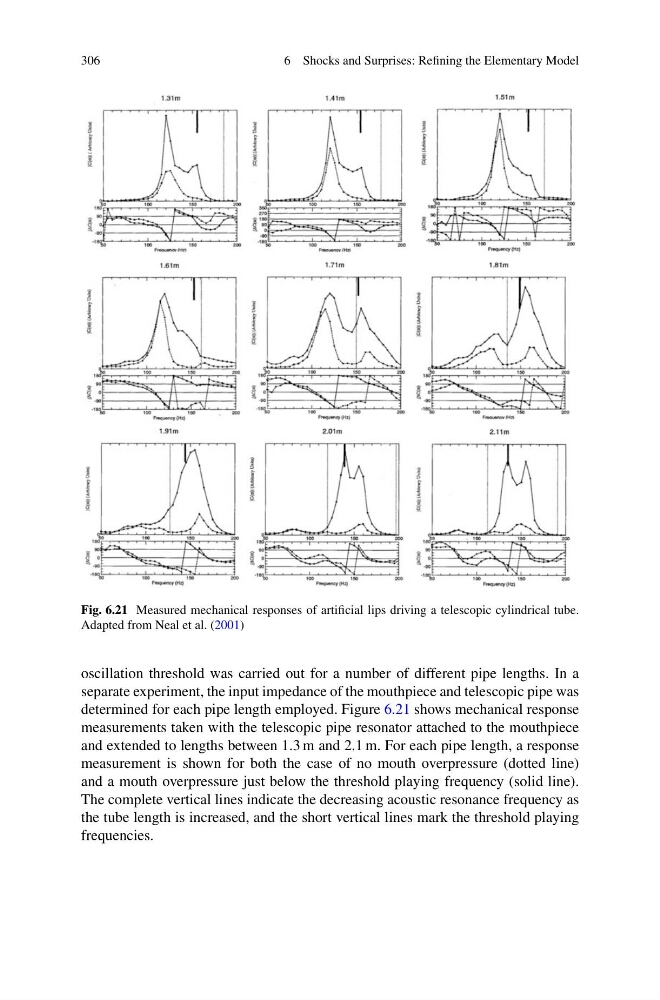
Fig. 6.21 Measured mechanical responses of artificial lips driving a telescopic cylindrical tube.
Adapted from Neal et al. (2001)
oscillation threshold was carried out for a number of different pipe lengths. In a
separate experiment, the input impedance of the mouthpiece and telescopic pipe was
determined for each pipe length employed. Figure 6.21 shows mechanical response
measurements taken with the telescopic pipe resonator attached to the mouthpiece
and extended to lengths between 1.3 m and 2.1 m. For each pipe length, a response
measurement is shown for both the case of no mouth overpressure (dotted line)
and a mouth overpressure just below the threshold playing frequency (solid line).
The complete vertical lines indicate the decreasing acoustic resonance frequency as
the tube length is increased, and the short vertical lines mark the threshold playing
frequencies.
6 Shocks and Surprises: Refining the Elementary Model
Fig. 6.21 Measured mechanical responses of artificial lips driving a telescopic cylindrical tube.
Adapted from Neal et al. (2001)
oscillation threshold was carried out for a number of different pipe lengths. In a
separate experiment, the input impedance of the mouthpiece and telescopic pipe was
determined for each pipe length employed. Figure 6.21 shows mechanical response
measurements taken with the telescopic pipe resonator attached to the mouthpiece
and extended to lengths between 1.3 m and 2.1 m. For each pipe length, a response
measurement is shown for both the case of no mouth overpressure (dotted line)
and a mouth overpressure just below the threshold playing frequency (solid line).
The complete vertical lines indicate the decreasing acoustic resonance frequency as
the tube length is increased, and the short vertical lines mark the threshold playing
frequencies.