

5.4 Going Further: From Linear Stability Analysis to Oscillation Regimes
249
The same exercise of reformulation is now presented using the ‘complex mode’
representation of the input impedance Z (see, e.g. Silva et al. (2014)). The modalfitted input impedance with N resonance modes is written as follows:
Z(ω) = Z c
N
n=1
C n
jω − s n
+
¯
C n
jω − ¯
s n
,
(5.33)
where s n and C n are the complex poles and the complex residues of the nth complex
mode, and ¯
s n and ¯
C n their respective complex conjugates. The characteristic
impedance of the resonator is Z c = ρc/S, where S is the input cross-section of
the bore at the mouthpiece rim.
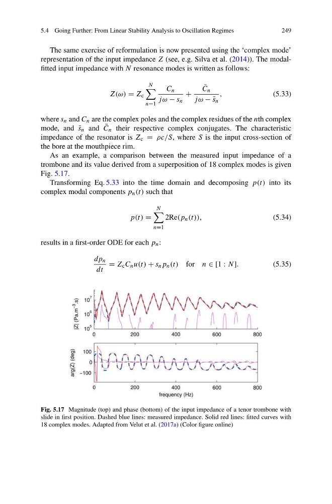
As an example, a comparison between the measured input impedance of a
trombone and its value derived from a superposition of 18 complex modes is given
Fig. 5.17.
Transforming Eq. 5.33 into the time domain and decomposing p(t) into its
complex modal components p n (t) such that
p(t) =
N
n=1
2Re(p n (t)),
(5.34)
results in a first-order ODE for each p n :
dp n
dt
= Z c C n u(t) + s n p n (t) for n ∈ [1 : N].
(5.35)
Fig. 5.17 Magnitude (top) and phase (bottom) of the input impedance of a tenor trombone with
slide in first position. Dashed blue lines: measured impedance. Solid red lines: fitted curves with
18 complex modes. Adapted from Velut et al. (2017a) (Color figure online)
249
The same exercise of reformulation is now presented using the ‘complex mode’
representation of the input impedance Z (see, e.g. Silva et al. (2014)). The modalfitted input impedance with N resonance modes is written as follows:
Z(ω) = Z c
N
n=1
C n
jω − s n
+
¯
C n
jω − ¯
s n
,
(5.33)
where s n and C n are the complex poles and the complex residues of the nth complex
mode, and ¯
s n and ¯
C n their respective complex conjugates. The characteristic
impedance of the resonator is Z c = ρc/S, where S is the input cross-section of
the bore at the mouthpiece rim.
As an example, a comparison between the measured input impedance of a
trombone and its value derived from a superposition of 18 complex modes is given
Fig. 5.17.
Transforming Eq. 5.33 into the time domain and decomposing p(t) into its
complex modal components p n (t) such that
p(t) =
N
n=1
2Re(p n (t)),
(5.34)
results in a first-order ODE for each p n :
dp n
dt
= Z c C n u(t) + s n p n (t) for n ∈ [1 : N].
(5.35)
Fig. 5.17 Magnitude (top) and phase (bottom) of the input impedance of a tenor trombone with
slide in first position. Dashed blue lines: measured impedance. Solid red lines: fitted curves with
18 complex modes. Adapted from Velut et al. (2017a) (Color figure online)