

210
4 After the Lips: Acoustic Resonances and Radiation
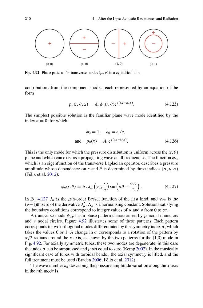
Fig. 4.92 Phase patterns for transverse modes (μ, ν) in a cylindrical tube
contributions from the component modes, each represented by an equation of the
form
p n (r, θ, x) = A n φ n (r, θ )e
j (ωt−k n x) .
(4.125)
The simplest possible solution is the familiar plane wave mode identified by the
index n = 0, for which
φ 0 = 1, k 0 = ω/c,
and p 0 (x) = A 0 e
j (ωt−k 0 x) .
(4.126)
This is the only mode for which the pressure distribution is uniform across the (r, θ )
plane and which can exist as a propagating wave at all frequencies. The function φ n ,
which is an eigenfunction of the transverse Laplacian operator, describes a pressure
amplitude whose dependence on r and θ is determined by three indices (μ, ν, σ )
(Félix et al. 2012):
φ n (r, θ ) = n J μ
γ μν
r
a
sin
μθ +
σ π
2
.
(4.127)
In Eq. 4.127 J μ is the μth-order Bessel function of the first kind, and γ μν is the
(ν +1)th zero of the derivative J
μ . n is a normalising constant. Solutions satisfying
the boundary conditions correspond to integer values of μ and ν from 0 to ∞.
A transverse mode φ μν has a phase pattern characterised by μ nodal diameters
and ν nodal circles. Figure 4.92 illustrates some of these patterns. Each pattern
corresponds to two orthogonal modes differentiated by the symmetry index σ , which
takes the values 0 or 1. A change in σ corresponds to a rotation of the pattern by
π/2 radians around the x axis, as shown by the two patterns for the (1,0) mode in
Fig. 4.92. For axially symmetric tubes, these two modes are degenerate; in this case
the index σ can be suppressed and μ set equal to zero (Kemp 2002). In the musically
significant case of tubes with toroidal bends , the axial symmetry is lifted, and the
full treatment must be used (Braden 2006; Félix et al. 2012).
The wave number k n describing the pressure amplitude variation along the x axis
in the nth mode is
4 After the Lips: Acoustic Resonances and Radiation
Fig. 4.92 Phase patterns for transverse modes (μ, ν) in a cylindrical tube
contributions from the component modes, each represented by an equation of the
form
p n (r, θ, x) = A n φ n (r, θ )e
j (ωt−k n x) .
(4.125)
The simplest possible solution is the familiar plane wave mode identified by the
index n = 0, for which
φ 0 = 1, k 0 = ω/c,
and p 0 (x) = A 0 e
j (ωt−k 0 x) .
(4.126)
This is the only mode for which the pressure distribution is uniform across the (r, θ )
plane and which can exist as a propagating wave at all frequencies. The function φ n ,
which is an eigenfunction of the transverse Laplacian operator, describes a pressure
amplitude whose dependence on r and θ is determined by three indices (μ, ν, σ )
(Félix et al. 2012):
φ n (r, θ ) = n J μ
γ μν
r
a
sin
μθ +
σ π
2
.
(4.127)
In Eq. 4.127 J μ is the μth-order Bessel function of the first kind, and γ μν is the
(ν +1)th zero of the derivative J
μ . n is a normalising constant. Solutions satisfying
the boundary conditions correspond to integer values of μ and ν from 0 to ∞.
A transverse mode φ μν has a phase pattern characterised by μ nodal diameters
and ν nodal circles. Figure 4.92 illustrates some of these patterns. Each pattern
corresponds to two orthogonal modes differentiated by the symmetry index σ , which
takes the values 0 or 1. A change in σ corresponds to a rotation of the pattern by
π/2 radians around the x axis, as shown by the two patterns for the (1,0) mode in
Fig. 4.92. For axially symmetric tubes, these two modes are degenerate; in this case
the index σ can be suppressed and μ set equal to zero (Kemp 2002). In the musically
significant case of tubes with toroidal bends , the axial symmetry is lifted, and the
full treatment must be used (Braden 2006; Félix et al. 2012).
The wave number k n describing the pressure amplitude variation along the x axis
in the nth mode is