

4.3 Bore Profiles of Brass Instruments
153
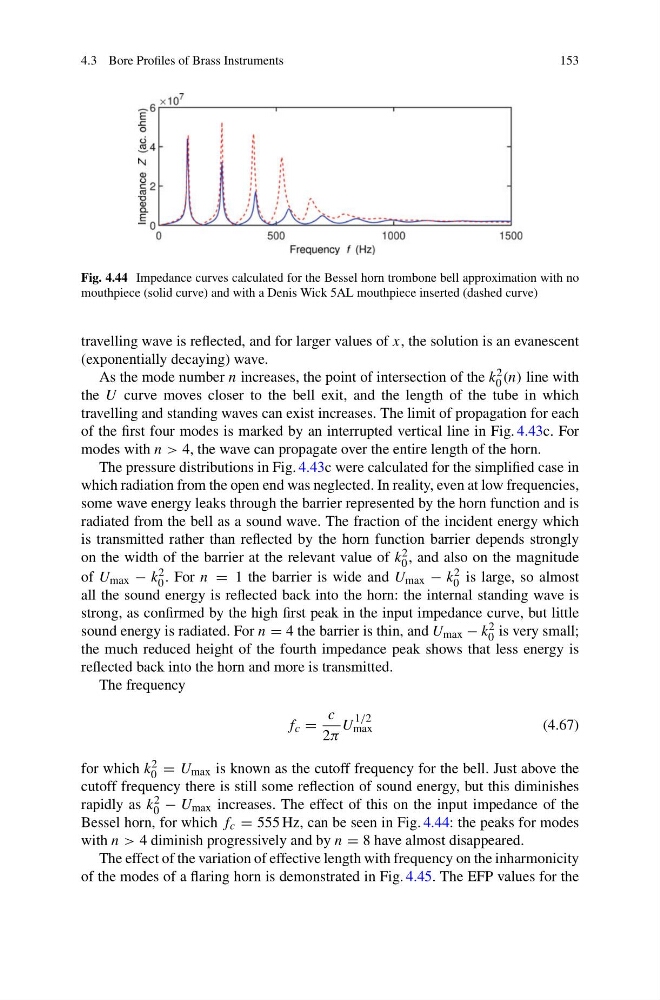
Fig. 4.44 Impedance curves calculated for the Bessel horn trombone bell approximation with no
mouthpiece (solid curve) and with a Denis Wick 5AL mouthpiece inserted (dashed curve)
travelling wave is reflected, and for larger values of x, the solution is an evanescent
(exponentially decaying) wave.
As the mode number n increases, the point of intersection of the k 2
0 (n) line with
the U curve moves closer to the bell exit, and the length of the tube in which
travelling and standing waves can exist increases. The limit of propagation for each
of the first four modes is marked by an interrupted vertical line in Fig. 4.43c. For
modes with n > 4, the wave can propagate over the entire length of the horn.
The pressure distributions in Fig. 4.43c were calculated for the simplified case in
which radiation from the open end was neglected. In reality, even at low frequencies,
some wave energy leaks through the barrier represented by the horn function and is
radiated from the bell as a sound wave. The fraction of the incident energy which
is transmitted rather than reflected by the horn function barrier depends strongly
on the width of the barrier at the relevant value of k 2
0 , and also on the magnitude
of U max − k 2
0 . For n = 1 the barrier is wide and U max − k 2
0 is large, so almost
all the sound energy is reflected back into the horn: the internal standing wave is
strong, as confirmed by the high first peak in the input impedance curve, but little
sound energy is radiated. For n = 4 the barrier is thin, and U max − k 2
0 is very small;
the much reduced height of the fourth impedance peak shows that less energy is
reflected back into the horn and more is transmitted.
The frequency
f c =
c
2π
U
1/2
max
(4.67)
for which k 2
0 = U max is known as the cutoff frequency for the bell. Just above the
cutoff frequency there is still some reflection of sound energy, but this diminishes
rapidly as k 2
0 − U max increases. The effect of this on the input impedance of the
Bessel horn, for which f c = 555 Hz, can be seen in Fig. 4.44: the peaks for modes
with n > 4 diminish progressively and by n = 8 have almost disappeared.
The effect of the variation of effective length with frequency on the inharmonicity
of the modes of a flaring horn is demonstrated in Fig. 4.45. The EFP values for the
153
Fig. 4.44 Impedance curves calculated for the Bessel horn trombone bell approximation with no
mouthpiece (solid curve) and with a Denis Wick 5AL mouthpiece inserted (dashed curve)
travelling wave is reflected, and for larger values of x, the solution is an evanescent
(exponentially decaying) wave.
As the mode number n increases, the point of intersection of the k 2
0 (n) line with
the U curve moves closer to the bell exit, and the length of the tube in which
travelling and standing waves can exist increases. The limit of propagation for each
of the first four modes is marked by an interrupted vertical line in Fig. 4.43c. For
modes with n > 4, the wave can propagate over the entire length of the horn.
The pressure distributions in Fig. 4.43c were calculated for the simplified case in
which radiation from the open end was neglected. In reality, even at low frequencies,
some wave energy leaks through the barrier represented by the horn function and is
radiated from the bell as a sound wave. The fraction of the incident energy which
is transmitted rather than reflected by the horn function barrier depends strongly
on the width of the barrier at the relevant value of k 2
0 , and also on the magnitude
of U max − k 2
0 . For n = 1 the barrier is wide and U max − k 2
0 is large, so almost
all the sound energy is reflected back into the horn: the internal standing wave is
strong, as confirmed by the high first peak in the input impedance curve, but little
sound energy is radiated. For n = 4 the barrier is thin, and U max − k 2
0 is very small;
the much reduced height of the fourth impedance peak shows that less energy is
reflected back into the horn and more is transmitted.
The frequency
f c =
c
2π
U
1/2
max
(4.67)
for which k 2
0 = U max is known as the cutoff frequency for the bell. Just above the
cutoff frequency there is still some reflection of sound energy, but this diminishes
rapidly as k 2
0 − U max increases. The effect of this on the input impedance of the
Bessel horn, for which f c = 555 Hz, can be seen in Fig. 4.44: the peaks for modes
with n > 4 diminish progressively and by n = 8 have almost disappeared.
The effect of the variation of effective length with frequency on the inharmonicity
of the modes of a flaring horn is demonstrated in Fig. 4.45. The EFP values for the