

4.3 Bore Profiles of Brass Instruments
135
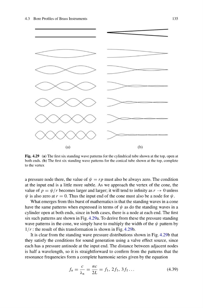
Fig. 4.29 (a) The first six standing wave patterns for the cylindrical tube shown at the top, open at
both ends. (b) The first six standing wave patterns for the conical tube shown at the top, complete
to the vertex
a pressure node there, the value of ψ = rp must also be always zero. The condition
at the input end is a little more subtle. As we approach the vertex of the cone, the
value of p = ψ/r becomes larger and larger; it will tend to infinity as r → 0 unless
ψ is also zero at r = 0. Thus the input end of the cone must also be a node for ψ.
What emerges from this burst of mathematics is that the standing waves in a cone
have the same patterns when expressed in terms of ψ as do the standing waves in a
cylinder open at both ends, since in both cases, there is a node at each end. The first
six such patterns are shown in Fig. 4.29a. To derive from these the pressure standing
wave patterns in the cone, we simply have to multiply the width of the ψ pattern by
1/r : the result of this transformation is shown in Fig. 4.29b.
It is clear from the standing wave pressure distributions shown in Fig. 4.29b that
they satisfy the conditions for sound generation using a valve effect source, since
each has a pressure antinode at the input end. The distance between adjacent nodes
is half a wavelength, so it is straightforward to confirm from the patterns that the
resonance frequencies form a complete harmonic series given by the equation
f n =
c
λ n
=
nc
2L
= f 1 , 2f 1 , 3f 1 . . .
(4.39)
135
Fig. 4.29 (a) The first six standing wave patterns for the cylindrical tube shown at the top, open at
both ends. (b) The first six standing wave patterns for the conical tube shown at the top, complete
to the vertex
a pressure node there, the value of ψ = rp must also be always zero. The condition
at the input end is a little more subtle. As we approach the vertex of the cone, the
value of p = ψ/r becomes larger and larger; it will tend to infinity as r → 0 unless
ψ is also zero at r = 0. Thus the input end of the cone must also be a node for ψ.
What emerges from this burst of mathematics is that the standing waves in a cone
have the same patterns when expressed in terms of ψ as do the standing waves in a
cylinder open at both ends, since in both cases, there is a node at each end. The first
six such patterns are shown in Fig. 4.29a. To derive from these the pressure standing
wave patterns in the cone, we simply have to multiply the width of the ψ pattern by
1/r : the result of this transformation is shown in Fig. 4.29b.
It is clear from the standing wave pressure distributions shown in Fig. 4.29b that
they satisfy the conditions for sound generation using a valve effect source, since
each has a pressure antinode at the input end. The distance between adjacent nodes
is half a wavelength, so it is straightforward to confirm from the patterns that the
resonance frequencies form a complete harmonic series given by the equation
f n =
c
λ n
=
nc
2L
= f 1 , 2f 1 , 3f 1 . . .
(4.39)