

4.2 Measuring Input Impedance
125
described with three calibrations (Gibiat and Laloë 1990) and four calibrations (van
Walstijn et al. 2005).
Two-microphone wave separation breaks down at frequencies for which the
microphone spacing is equal to an integer number of half wavelengths, since
the two microphones then give essentially the same information. This problem
can be partly overcome by using more than two microphones, and the ‘twomicrophone’ apparatus described by Gibiat and Laloë (1990) in practice included
four microphones with different spacings. Issues involved in the expansion of the
frequency bandwidth using multiple microphones are discussed by Kemp et al.
(2010).
4.2.4 Acoustic Pulse Reflectometry
The technique known as acoustic pulse reflectometry (APR) uses an experimental
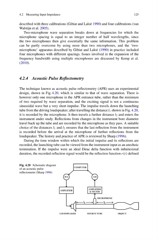
design, shown in Fig. 4.20, which is similar to that of wave separation. There is
however only one microphone in the APR entrance tube, rather than the minimum
of two required by wave separation, and the exciting signal is not a continuous
sinusoidal wave but a very short impulse. The impulse travels down the launching
tube from the driving loudspeaker; after travelling the distance l 1 shown in Fig. 4.20,
it is recorded by the microphone. It then travels a further distance l 2 and enters the
instrument under study. Reflections from changes in the instrument bore diameter
travel back up the tube and are recorded by the microphone as they pass. A suitable
choice of the distances l 1 and l 2 ensures that the last reflection from the instrument
is recorded before the arrival at the microphone of further reflections from the
loudspeaker. The history and practice of APR is reviewed by Sharp (1996).
During the time window within which the initial impulse and its reflections are
recorded, the launching tube can be viewed from the instrument input as an anechoic
termination. If the impulse were an ideal Dirac delta function with infinitesimal
duration, the recorded reflection signal would be the reflection function r(t) defined
Fig. 4.20 Schematic diagram
of an acoustic pulse
reflectometer (Sharp 1996)
125
described with three calibrations (Gibiat and Laloë 1990) and four calibrations (van
Walstijn et al. 2005).
Two-microphone wave separation breaks down at frequencies for which the
microphone spacing is equal to an integer number of half wavelengths, since
the two microphones then give essentially the same information. This problem
can be partly overcome by using more than two microphones, and the ‘twomicrophone’ apparatus described by Gibiat and Laloë (1990) in practice included
four microphones with different spacings. Issues involved in the expansion of the
frequency bandwidth using multiple microphones are discussed by Kemp et al.
(2010).
4.2.4 Acoustic Pulse Reflectometry
The technique known as acoustic pulse reflectometry (APR) uses an experimental
design, shown in Fig. 4.20, which is similar to that of wave separation. There is
however only one microphone in the APR entrance tube, rather than the minimum
of two required by wave separation, and the exciting signal is not a continuous
sinusoidal wave but a very short impulse. The impulse travels down the launching
tube from the driving loudspeaker; after travelling the distance l 1 shown in Fig. 4.20,
it is recorded by the microphone. It then travels a further distance l 2 and enters the
instrument under study. Reflections from changes in the instrument bore diameter
travel back up the tube and are recorded by the microphone as they pass. A suitable
choice of the distances l 1 and l 2 ensures that the last reflection from the instrument
is recorded before the arrival at the microphone of further reflections from the
loudspeaker. The history and practice of APR is reviewed by Sharp (1996).
During the time window within which the initial impulse and its reflections are
recorded, the launching tube can be viewed from the instrument input as an anechoic
termination. If the impulse were an ideal Dirac delta function with infinitesimal
duration, the recorded reflection signal would be the reflection function r(t) defined
Fig. 4.20 Schematic diagram
of an acoustic pulse
reflectometer (Sharp 1996)