

122
4 After the Lips: Acoustic Resonances and Radiation
ing cylinder (Backus 1974). Detailed measurements of the input impedances of
trumpets, trombones and french horns were subsequently made by Backus using
a version of this equipment (Backus 1976). Further improvements to the capillary
technique were proposed by Caussé et al. (1984) and Kergomard and Caussé (1986),
and many research groups subsequently developed equipment of this type.
In most applications of the capillary method, the injected pressure signal is a
sine sweep. The research team led by Joe Wolfe at the University of New South
Wales in Sydney has adopted a different approach, in which the exciting signal is a
computer-generated sum of sinusoidal frequency components at intervals of a few
Hz (Dickens et al. 2007). The frequency spectrum of the signal can be tailored to
maximise the signal-to-noise ratio, which has been a valuable feature in studies of
the effects of player windway resonances during performance (see Sect. 6.3).
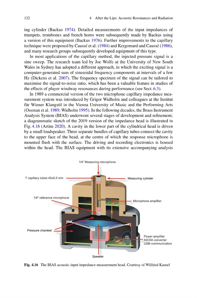
In 1989 a commercial version of the two microphone capillary impedance measurement system was introduced by Grigor Widholm and colleagues at the Institut
für Wiener Klangstil in the Vienna University of Music and the Performing Arts
(Ossman et al. 1989; Widholm 1995). In the following decades, the Brass Instrument
Analysis System (BIAS) underwent several stages of development and refinement;
a diagrammatic sketch of the 2019 version of the impedance head is illustrated in
Fig. 4.16 (Artim 2020). A cavity in the lower part of the cylindrical head is driven
by a small loudspeaker. Three separate bundles of capillary tubes connect the cavity
to the upper face of the head, at the centre of which the response microphone is
mounted flush with the surface. The driving and recording electronics is housed
within the head. The BIAS equipment with its extensive accompanying analysis
Fig. 4.16 The BIAS acoustic input impedance measurement head. Courtesy of Wilfried Kausel
4 After the Lips: Acoustic Resonances and Radiation
ing cylinder (Backus 1974). Detailed measurements of the input impedances of
trumpets, trombones and french horns were subsequently made by Backus using
a version of this equipment (Backus 1976). Further improvements to the capillary
technique were proposed by Caussé et al. (1984) and Kergomard and Caussé (1986),
and many research groups subsequently developed equipment of this type.
In most applications of the capillary method, the injected pressure signal is a
sine sweep. The research team led by Joe Wolfe at the University of New South
Wales in Sydney has adopted a different approach, in which the exciting signal is a
computer-generated sum of sinusoidal frequency components at intervals of a few
Hz (Dickens et al. 2007). The frequency spectrum of the signal can be tailored to
maximise the signal-to-noise ratio, which has been a valuable feature in studies of
the effects of player windway resonances during performance (see Sect. 6.3).
In 1989 a commercial version of the two microphone capillary impedance measurement system was introduced by Grigor Widholm and colleagues at the Institut
für Wiener Klangstil in the Vienna University of Music and the Performing Arts
(Ossman et al. 1989; Widholm 1995). In the following decades, the Brass Instrument
Analysis System (BIAS) underwent several stages of development and refinement;
a diagrammatic sketch of the 2019 version of the impedance head is illustrated in
Fig. 4.16 (Artim 2020). A cavity in the lower part of the cylindrical head is driven
by a small loudspeaker. Three separate bundles of capillary tubes connect the cavity
to the upper face of the head, at the centre of which the response microphone is
mounted flush with the surface. The driving and recording electronics is housed
within the head. The BIAS equipment with its extensive accompanying analysis
Fig. 4.16 The BIAS acoustic input impedance measurement head. Courtesy of Wilfried Kausel