

4.1 Internal Sounds in Brass Instruments
111
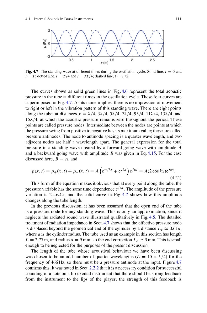
Fig. 4.7 The standing wave at different times during the oscillation cycle. Solid line, t = 0 and
t = T ; dotted line, t = T /4 and t = 3T /4; dashed line, t = T /2
The curves shown as solid green lines in Fig. 4.6 represent the total acoustic
pressure in the tube at different times in the oscillation cycle. These four curves are
superimposed in Fig. 4.7. As its name implies, there is no impression of movement
to right or left in the vibration pattern of this standing wave. There are eight points
along the tube, at distances x = λ/4, 3λ/4, 5λ/4, 7λ/4, 9λ/4, 11λ/4, 13λ/4, and
15λ/4, at which the acoustic pressure remains zero throughout the period. These
points are called pressure nodes. Intermediate between the nodes are points at which
the pressure swing from positive to negative has its maximum value; these are called
pressure antinodes. The node to antinode spacing is a quarter wavelength, and two
adjacent nodes are half a wavelength apart. The general expression for the total
pressure in a standing wave created by a forward-going wave with amplitude A
and a backward going wave with amplitude B was given in Eq. 4.15. For the case
discussed here, B = A, and
p(x, t) = p + (x, t) + p − (x, t) = A
e
−jkx
+ e
jkx
e
jωt
= A(2 cos kx)e
jωt .
(4.21)
This form of the equation makes it obvious that at every point along the tube, the
pressure variable has the same time dependence e jωt . The amplitude of the pressure
variation is 2 cos kx, and the solid curve in Fig. 4.7 shows how this amplitude
changes along the tube length.
In the previous discussion, it has been assumed that the open end of the tube
is a pressure node for any standing wave. This is only an approximation, since it
neglects the radiated sound wave illustrated qualitatively in Fig. 4.5. The detailed
treatment of radiation impedance in Sect. 4.7 shows that the effective pressure node
is displaced beyond the geometrical end of the cylinder by a distance L e 0.61a,
where a is the cylinder radius. The tube used as an example in this section has length
L = 2.77 m, and radius a = 5 mm, so the end correction L e 3 mm. This is small
enough to be neglected for the purposes of the present discussion.
The length of the tube whose acoustical behaviour we have been discussing
was chosen to be an odd number of quarter wavelengths (L = 15 × λ/4) for the
frequency of 466 Hz, so there must be a pressure antinode at the input. Figure 4.7
confirms this. It was noted in Sect. 2.2.2 that it is a necessary condition for successful
sounding of a note on a lip-excited instrument that there should be strong feedback
from the instrument to the lips of the player; the strength of this feedback is
111
Fig. 4.7 The standing wave at different times during the oscillation cycle. Solid line, t = 0 and
t = T ; dotted line, t = T /4 and t = 3T /4; dashed line, t = T /2
The curves shown as solid green lines in Fig. 4.6 represent the total acoustic
pressure in the tube at different times in the oscillation cycle. These four curves are
superimposed in Fig. 4.7. As its name implies, there is no impression of movement
to right or left in the vibration pattern of this standing wave. There are eight points
along the tube, at distances x = λ/4, 3λ/4, 5λ/4, 7λ/4, 9λ/4, 11λ/4, 13λ/4, and
15λ/4, at which the acoustic pressure remains zero throughout the period. These
points are called pressure nodes. Intermediate between the nodes are points at which
the pressure swing from positive to negative has its maximum value; these are called
pressure antinodes. The node to antinode spacing is a quarter wavelength, and two
adjacent nodes are half a wavelength apart. The general expression for the total
pressure in a standing wave created by a forward-going wave with amplitude A
and a backward going wave with amplitude B was given in Eq. 4.15. For the case
discussed here, B = A, and
p(x, t) = p + (x, t) + p − (x, t) = A
e
−jkx
+ e
jkx
e
jωt
= A(2 cos kx)e
jωt .
(4.21)
This form of the equation makes it obvious that at every point along the tube, the
pressure variable has the same time dependence e jωt . The amplitude of the pressure
variation is 2 cos kx, and the solid curve in Fig. 4.7 shows how this amplitude
changes along the tube length.
In the previous discussion, it has been assumed that the open end of the tube
is a pressure node for any standing wave. This is only an approximation, since it
neglects the radiated sound wave illustrated qualitatively in Fig. 4.5. The detailed
treatment of radiation impedance in Sect. 4.7 shows that the effective pressure node
is displaced beyond the geometrical end of the cylinder by a distance L e 0.61a,
where a is the cylinder radius. The tube used as an example in this section has length
L = 2.77 m, and radius a = 5 mm, so the end correction L e 3 mm. This is small
enough to be neglected for the purposes of the present discussion.
The length of the tube whose acoustical behaviour we have been discussing
was chosen to be an odd number of quarter wavelengths (L = 15 × λ/4) for the
frequency of 466 Hz, so there must be a pressure antinode at the input. Figure 4.7
confirms this. It was noted in Sect. 2.2.2 that it is a necessary condition for successful
sounding of a note on a lip-excited instrument that there should be strong feedback
from the instrument to the lips of the player; the strength of this feedback is