

3.3 Mission Analysis
61
3.3.4 Analysis of Environment Effects
It was necessary for the system design of lunar lander to analyze lunar terrain, regolith
on landing site.
1. Analysis of landing site effects.
1) Analysis of elevation and its effect along powered descent path.
During the powered descent, the height relative to lunar surface should be measured
by sensors onboard lunar lander. So the elevation along the powered descent path
would greatly affect the safety of powered descent, control scheme and propellant
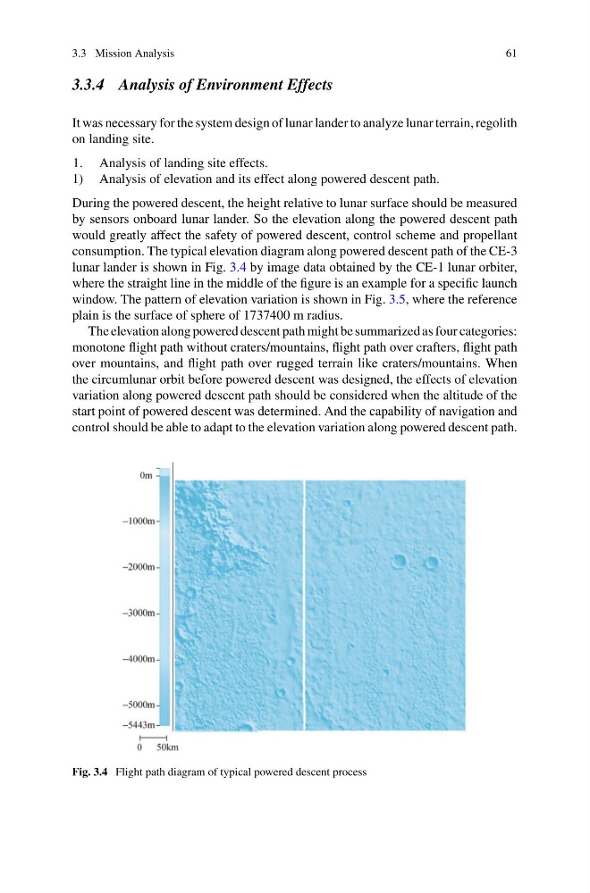
consumption. The typical elevation diagram along powered descent path of the CE-3
lunar lander is shown in Fig. 3.4 by image data obtained by the CE-1 lunar orbiter,
where the straight line in the middle of the figure is an example for a specific launch
window. The pattern of elevation variation is shown in Fig. 3.5, where the reference
plain is the surface of sphere of 1737400 m radius.
The elevation along powered descent path might be summarized as four categories:
monotone flight path without craters/mountains, flight path over crafters, flight path
over mountains, and flight path over rugged terrain like craters/mountains. When
the circumlunar orbit before powered descent was designed, the effects of elevation
variation along powered descent path should be considered when the altitude of the
start point of powered descent was determined. And the capability of navigation and
control should be able to adapt to the elevation variation along powered descent path.
Fig. 3.4 Flight path diagram of typical powered descent process
61
3.3.4 Analysis of Environment Effects
It was necessary for the system design of lunar lander to analyze lunar terrain, regolith
on landing site.
1. Analysis of landing site effects.
1) Analysis of elevation and its effect along powered descent path.
During the powered descent, the height relative to lunar surface should be measured
by sensors onboard lunar lander. So the elevation along the powered descent path
would greatly affect the safety of powered descent, control scheme and propellant
consumption. The typical elevation diagram along powered descent path of the CE-3
lunar lander is shown in Fig. 3.4 by image data obtained by the CE-1 lunar orbiter,
where the straight line in the middle of the figure is an example for a specific launch
window. The pattern of elevation variation is shown in Fig. 3.5, where the reference
plain is the surface of sphere of 1737400 m radius.
The elevation along powered descent path might be summarized as four categories:
monotone flight path without craters/mountains, flight path over crafters, flight path
over mountains, and flight path over rugged terrain like craters/mountains. When
the circumlunar orbit before powered descent was designed, the effects of elevation
variation along powered descent path should be considered when the altitude of the
start point of powered descent was determined. And the capability of navigation and
control should be able to adapt to the elevation variation along powered descent path.
Fig. 3.4 Flight path diagram of typical powered descent process