

538
16 Scientific Instrument Technology of Lunar Lander
(1) In the darkroom, the test instrument was connected as shown in Fig. 16.1. The
position of the tested camera was adjusted, so that the entrance pupil center
was consistent with the radiation opening center of the solar simulator; the
optical bar and the camera temperature monitoring equipment were set up,
and the cable between the camera and the computer and the image acquisition
equipment was connected.
(2) Set the camera exposure time, collect the dark current image data of the camera,
and the average of the multi-group dark current images was the camera dark
current.
(3) Turn on the power of the solar simulator, and the power current should not
be less than 70% of the rated current value of the light source, and then
measured the spectral radiance of the radiation opening of the solar simulator
after stabilization.
(4) Set the camera exposure time and collected camera image data.
(5) Check the temperature monitoring value of the camera and determine whether
to collect the next set of calibration data.
(6) Change the radiance level of the solar simulator, repeated steps (3)~(5) until
all the calibration data of the radiance level are collected.
The image data was obtained by subtracting the dark current from the image under
the different radiance illumination conditions, and the relative calibration coefficients
of each pixel were obtained by using the least square method.
2) Principle and method of absolute radiation calibration
The absolute radiation calibration is the quantitative relationship between the output
of the camera and the input radiation brightness under uniform irradiation.
In absolute calibration, the test method was the same as shown in Fig. 16.1. Under
the conditions of different exposure time and different radiance, the image data were
collected, and the absolute calibration coefficient was calculated after the calibration
of the flat field.
3) Principle and method for interior orientation elements calibration
The element of interior orientation calibration was to measure the camera’s focal
length and the main point internal parameters.
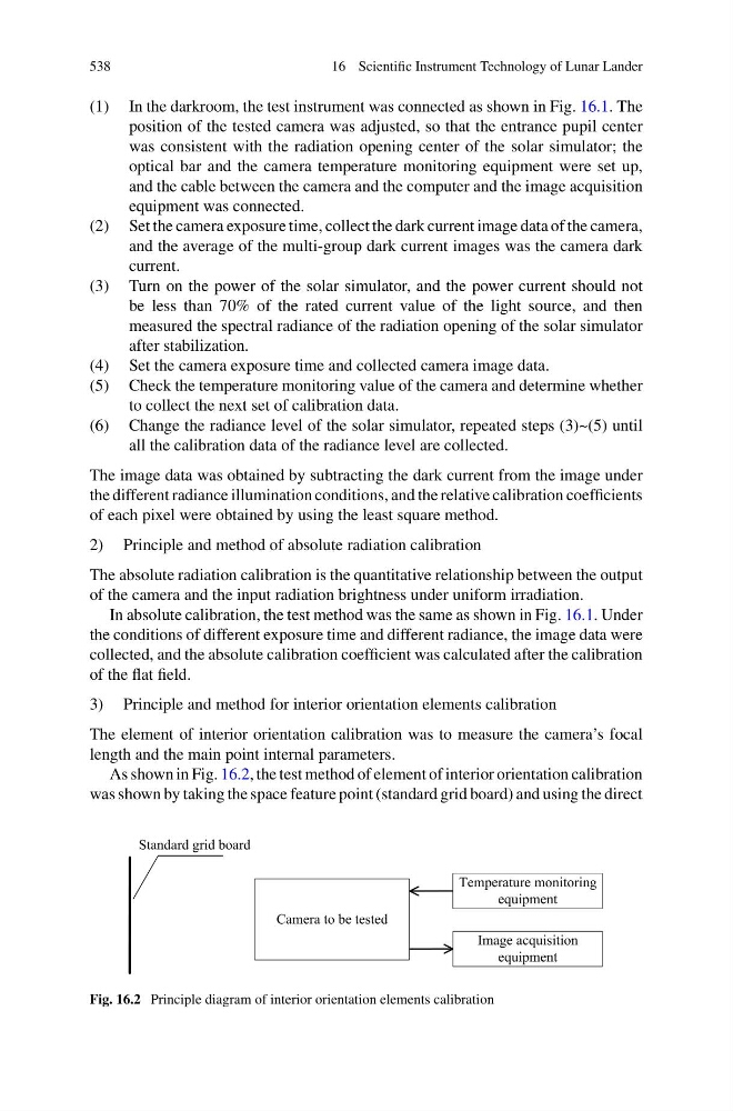
As shown in Fig. 16.2, the test method of element of interior orientation calibration
was shown by taking the space feature point (standard grid board) and using the direct
Camera to be tested
Image acquisition
equipment
Temperature monitoring
equipment
Standard grid board
Fig. 16.2 Principle diagram of interior orientation elements calibration
16 Scientific Instrument Technology of Lunar Lander
(1) In the darkroom, the test instrument was connected as shown in Fig. 16.1. The
position of the tested camera was adjusted, so that the entrance pupil center
was consistent with the radiation opening center of the solar simulator; the
optical bar and the camera temperature monitoring equipment were set up,
and the cable between the camera and the computer and the image acquisition
equipment was connected.
(2) Set the camera exposure time, collect the dark current image data of the camera,
and the average of the multi-group dark current images was the camera dark
current.
(3) Turn on the power of the solar simulator, and the power current should not
be less than 70% of the rated current value of the light source, and then
measured the spectral radiance of the radiation opening of the solar simulator
after stabilization.
(4) Set the camera exposure time and collected camera image data.
(5) Check the temperature monitoring value of the camera and determine whether
to collect the next set of calibration data.
(6) Change the radiance level of the solar simulator, repeated steps (3)~(5) until
all the calibration data of the radiance level are collected.
The image data was obtained by subtracting the dark current from the image under
the different radiance illumination conditions, and the relative calibration coefficients
of each pixel were obtained by using the least square method.
2) Principle and method of absolute radiation calibration
The absolute radiation calibration is the quantitative relationship between the output
of the camera and the input radiation brightness under uniform irradiation.
In absolute calibration, the test method was the same as shown in Fig. 16.1. Under
the conditions of different exposure time and different radiance, the image data were
collected, and the absolute calibration coefficient was calculated after the calibration
of the flat field.
3) Principle and method for interior orientation elements calibration
The element of interior orientation calibration was to measure the camera’s focal
length and the main point internal parameters.
As shown in Fig. 16.2, the test method of element of interior orientation calibration
was shown by taking the space feature point (standard grid board) and using the direct
Camera to be tested
Image acquisition
equipment
Temperature monitoring
equipment
Standard grid board
Fig. 16.2 Principle diagram of interior orientation elements calibration