

15.2 Development Status
487
vehicle through two connection points. The line between gimbal spreader and two
connection points passed through mass center of the test vehicle. The gimbal spreader
could provide pith, yaw and roll DOF. The other end of the rope was connected with
the lift unit of the crane. The lift unit could control the rope to move upward or
downward by servo control system. The lift force of the rope could be maintained
by force sensor and server control unit, so as to ensure that the lift force was 5/6
weight of the test vehicle. The crane could move in two DOF on the horizontal
plane provided by the gantry structure, which could ensure that the lift force should
be always vertical and upward by tracking position change of the test vehicle with
angle sensor on the rope [1].
2. LLRV
The LLRV was designed to simulate final flight trajectory of lunar soft landing
process, and it could also help to train the astronaut capability to control the lunar
module during soft landing and lift-off on lunar surface. The LLRV could simulate
the landing process when the altitude was about 457.5 m, including hovering and
horizontal motion, as well as lift-off on lunar surface, which could be applied to train
the astronaut to control the lunar module to hover down and find landing site. The
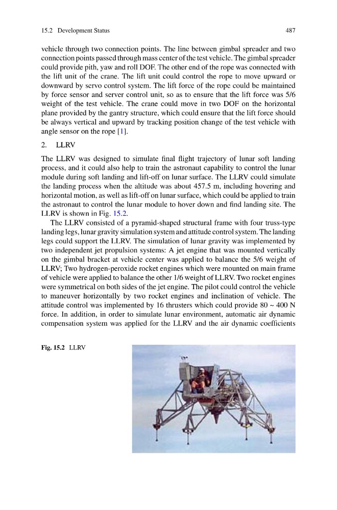
LLRV is shown in Fig. 15.2.
The LLRV consisted of a pyramid-shaped structural frame with four truss-type
landing legs, lunar gravity simulation system and attitude control system. The landing
legs could support the LLRV. The simulation of lunar gravity was implemented by
two independent jet propulsion systems: A jet engine that was mounted vertically
on the gimbal bracket at vehicle center was applied to balance the 5/6 weight of
LLRV; Two hydrogen-peroxide rocket engines which were mounted on main frame
of vehicle were applied to balance the other 1/6 weight of LLRV. Two rocket engines
were symmetrical on both sides of the jet engine. The pilot could control the vehicle
to maneuver horizontally by two rocket engines and inclination of vehicle. The
attitude control was implemented by 16 thrusters which could provide 80 ~ 400 N
force. In addition, in order to simulate lunar environment, automatic air dynamic
compensation system was applied for the LLRV and the air dynamic coefficients
Fig. 15.2 LLRV
487
vehicle through two connection points. The line between gimbal spreader and two
connection points passed through mass center of the test vehicle. The gimbal spreader
could provide pith, yaw and roll DOF. The other end of the rope was connected with
the lift unit of the crane. The lift unit could control the rope to move upward or
downward by servo control system. The lift force of the rope could be maintained
by force sensor and server control unit, so as to ensure that the lift force was 5/6
weight of the test vehicle. The crane could move in two DOF on the horizontal
plane provided by the gantry structure, which could ensure that the lift force should
be always vertical and upward by tracking position change of the test vehicle with
angle sensor on the rope [1].
2. LLRV
The LLRV was designed to simulate final flight trajectory of lunar soft landing
process, and it could also help to train the astronaut capability to control the lunar
module during soft landing and lift-off on lunar surface. The LLRV could simulate
the landing process when the altitude was about 457.5 m, including hovering and
horizontal motion, as well as lift-off on lunar surface, which could be applied to train
the astronaut to control the lunar module to hover down and find landing site. The
LLRV is shown in Fig. 15.2.
The LLRV consisted of a pyramid-shaped structural frame with four truss-type
landing legs, lunar gravity simulation system and attitude control system. The landing
legs could support the LLRV. The simulation of lunar gravity was implemented by
two independent jet propulsion systems: A jet engine that was mounted vertically
on the gimbal bracket at vehicle center was applied to balance the 5/6 weight of
LLRV; Two hydrogen-peroxide rocket engines which were mounted on main frame
of vehicle were applied to balance the other 1/6 weight of LLRV. Two rocket engines
were symmetrical on both sides of the jet engine. The pilot could control the vehicle
to maneuver horizontally by two rocket engines and inclination of vehicle. The
attitude control was implemented by 16 thrusters which could provide 80 ~ 400 N
force. In addition, in order to simulate lunar environment, automatic air dynamic
compensation system was applied for the LLRV and the air dynamic coefficients
Fig. 15.2 LLRV