

454
13 Metrology Technology of Lunar Lander
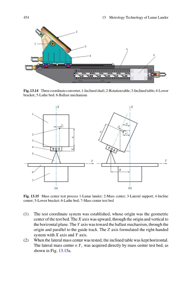
Fig. 13.14 Three coordinate converter, 1-Inclined shaft; 2-Rotation table; 3-Inclined table; 4-Lower
bracket; 5-Lathe bed; 6-Ballast mechanism
Fig. 13.15 Mass center test process 1-Lunar lander; 2-Mass center; 3-Lateral support; 4-Incline
center; 5-Lower bracket; 6-Lathe bed; 7-Mass center test bed
(1) The test coordinate system was established, whose origin was the geometric
center of the test bed. The X axis was upward, through the origin and vertical to
the horizontal plane. The Y axis was toward the ballast mechanism, through the
origin and parallel to the guide track. The Z axis formulated the right-handed
system with X axis and Y axis.
(2) When the lateral mass center was tested, the inclined table was kept horizontal.
The lateral mass center o Y c was acquired directly by mass center test bed, as
shown in Fig. 13.15a.
13 Metrology Technology of Lunar Lander
Fig. 13.14 Three coordinate converter, 1-Inclined shaft; 2-Rotation table; 3-Inclined table; 4-Lower
bracket; 5-Lathe bed; 6-Ballast mechanism
Fig. 13.15 Mass center test process 1-Lunar lander; 2-Mass center; 3-Lateral support; 4-Incline
center; 5-Lower bracket; 6-Lathe bed; 7-Mass center test bed
(1) The test coordinate system was established, whose origin was the geometric
center of the test bed. The X axis was upward, through the origin and vertical to
the horizontal plane. The Y axis was toward the ballast mechanism, through the
origin and parallel to the guide track. The Z axis formulated the right-handed
system with X axis and Y axis.
(2) When the lateral mass center was tested, the inclined table was kept horizontal.
The lateral mass center o Y c was acquired directly by mass center test bed, as
shown in Fig. 13.15a.