

13.4 Application of Special Measurement Technology
447
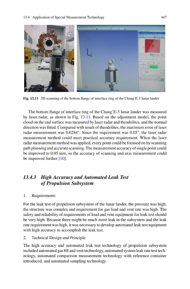
Fig. 13.11 3D scanning of the bottom flange of interface ring of the Chang’E-3 lunar lander
The bottom flange of interface ring of the Chang’E-3 lunar lander was measured
by laser radar, as shown in Fig. 13.11. Based on the adjustment model, the point
cloud on the end surface was measured by laser radar and theodolites, and the normal
direction was fitted. Compared with result of theodolites, the maximum error of laser
radar measurement was 0.0284°. Since the requirement was 0.05°, the laser radar
measurement method could meet practical accuracy requirement. When the laser
radar measurement method was applied, every point could be focused on by scanning
path planning and accurate scanning. The measurement accuracy of single point could
be improved to 0.05 mm, so the accuracy of scanning and axis measurement could
be improved further [10].
13.4.3 High Accuracy and Automated Leak Test
of Propulsion Subsystem
1. Requirements
For the leak test of propulsion subsystem of the lunar lander, the pressure was high,
the structure was complex and requirement for gas load and vent rate was high. The
safety and reliability of requirements of load and vent equipment for leak test should
be very high. Because there might be much more leak in the subsystem and the leak
rate requirement was high, it was necessary to develop automated leak test equipment
with high accuracy to accomplish the leak test.
2. Technical Design and Principle
The high accuracy and automated leak test technology of propulsion subsystem
included automated gas fill and vent technology, automated system leak rate test technology, automated comparison measurement technology with reference container
introduced, and automated sampling technology.
447
Fig. 13.11 3D scanning of the bottom flange of interface ring of the Chang’E-3 lunar lander
The bottom flange of interface ring of the Chang’E-3 lunar lander was measured
by laser radar, as shown in Fig. 13.11. Based on the adjustment model, the point
cloud on the end surface was measured by laser radar and theodolites, and the normal
direction was fitted. Compared with result of theodolites, the maximum error of laser
radar measurement was 0.0284°. Since the requirement was 0.05°, the laser radar
measurement method could meet practical accuracy requirement. When the laser
radar measurement method was applied, every point could be focused on by scanning
path planning and accurate scanning. The measurement accuracy of single point could
be improved to 0.05 mm, so the accuracy of scanning and axis measurement could
be improved further [10].
13.4.3 High Accuracy and Automated Leak Test
of Propulsion Subsystem
1. Requirements
For the leak test of propulsion subsystem of the lunar lander, the pressure was high,
the structure was complex and requirement for gas load and vent rate was high. The
safety and reliability of requirements of load and vent equipment for leak test should
be very high. Because there might be much more leak in the subsystem and the leak
rate requirement was high, it was necessary to develop automated leak test equipment
with high accuracy to accomplish the leak test.
2. Technical Design and Principle
The high accuracy and automated leak test technology of propulsion subsystem
included automated gas fill and vent technology, automated system leak rate test technology, automated comparison measurement technology with reference container
introduced, and automated sampling technology.