

13.4 Application of Special Measurement Technology
443
was analyzed. Then the impact of the common point density on the transformation accuracy could be determined. The simulation analysis showed that the more
dispersed the common points, the higher the transformation accuracy. The analysis
showed that when the measuring accuracy was at the same level, the accuracy of
the coordinate transformation of the sparse common points was higher than that of
the dense common points. When the measurement was conducted, a highly accurate
measurement control field was built by the laser tracker system. The common points
should be distributed around the objects to be measured and in the whole measuring
space.
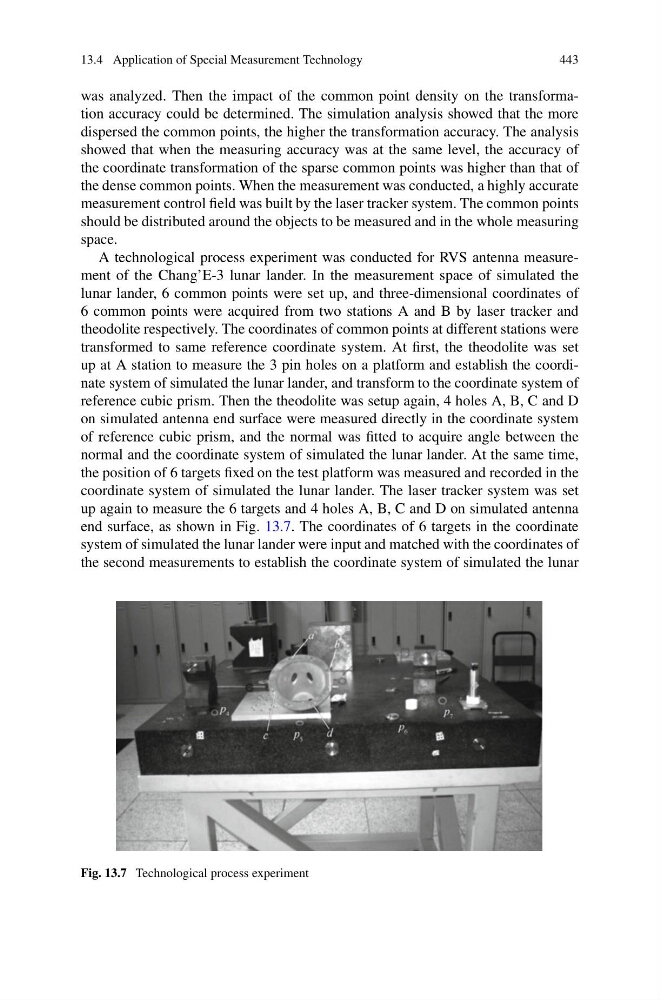
A technological process experiment was conducted for RVS antenna measurement of the Chang’E-3 lunar lander. In the measurement space of simulated the
lunar lander, 6 common points were set up, and three-dimensional coordinates of
6 common points were acquired from two stations A and B by laser tracker and
theodolite respectively. The coordinates of common points at different stations were
transformed to same reference coordinate system. At first, the theodolite was set
up at A station to measure the 3 pin holes on a platform and establish the coordinate system of simulated the lunar lander, and transform to the coordinate system of
reference cubic prism. Then the theodolite was setup again, 4 holes A, B, C and D
on simulated antenna end surface were measured directly in the coordinate system
of reference cubic prism, and the normal was fitted to acquire angle between the
normal and the coordinate system of simulated the lunar lander. At the same time,
the position of 6 targets fixed on the test platform was measured and recorded in the
coordinate system of simulated the lunar lander. The laser tracker system was set
up again to measure the 6 targets and 4 holes A, B, C and D on simulated antenna
end surface, as shown in Fig. 13.7. The coordinates of 6 targets in the coordinate
system of simulated the lunar lander were input and matched with the coordinates of
the second measurements to establish the coordinate system of simulated the lunar
Fig. 13.7 Technological process experiment
443
was analyzed. Then the impact of the common point density on the transformation accuracy could be determined. The simulation analysis showed that the more
dispersed the common points, the higher the transformation accuracy. The analysis
showed that when the measuring accuracy was at the same level, the accuracy of
the coordinate transformation of the sparse common points was higher than that of
the dense common points. When the measurement was conducted, a highly accurate
measurement control field was built by the laser tracker system. The common points
should be distributed around the objects to be measured and in the whole measuring
space.
A technological process experiment was conducted for RVS antenna measurement of the Chang’E-3 lunar lander. In the measurement space of simulated the
lunar lander, 6 common points were set up, and three-dimensional coordinates of
6 common points were acquired from two stations A and B by laser tracker and
theodolite respectively. The coordinates of common points at different stations were
transformed to same reference coordinate system. At first, the theodolite was set
up at A station to measure the 3 pin holes on a platform and establish the coordinate system of simulated the lunar lander, and transform to the coordinate system of
reference cubic prism. Then the theodolite was setup again, 4 holes A, B, C and D
on simulated antenna end surface were measured directly in the coordinate system
of reference cubic prism, and the normal was fitted to acquire angle between the
normal and the coordinate system of simulated the lunar lander. At the same time,
the position of 6 targets fixed on the test platform was measured and recorded in the
coordinate system of simulated the lunar lander. The laser tracker system was set
up again to measure the 6 targets and 4 holes A, B, C and D on simulated antenna
end surface, as shown in Fig. 13.7. The coordinates of 6 targets in the coordinate
system of simulated the lunar lander were input and matched with the coordinates of
the second measurements to establish the coordinate system of simulated the lunar
Fig. 13.7 Technological process experiment