

386
11 Landing Gear Technology of Lunar Lander
of aluminum alloy, while the universal joint and ball joint are made of
titanium alloy.
4) Footpad design.
(1) Keys. It included anti-subsidence design, strength design, cushion design
and design of lunar surface sensing probe. Anti-subsidence design refers
to selection of a reasonable supporting area. Strength design was structural
design to meet requirement of strength margin. Cushion design was to
ensure that the footpad periphery has reasonable capacity of deformation.
(2) Anti-subsidence design. The base area of the footpad is determined by
anticipated impact load, relation of landing surface strength versus depth
of subsidence and acceptable depth of subsidence.
(3) Cushion design. Aluminum honeycomb with certain strength was selected
to fill in the footpad periphery so as to provide auxiliary cushion for
horizontal impact load.
(4) Design of lunar surface sensing probe. The lunar surface sensing probe
was a probe or switch installed on the bottom surface of the footpad.
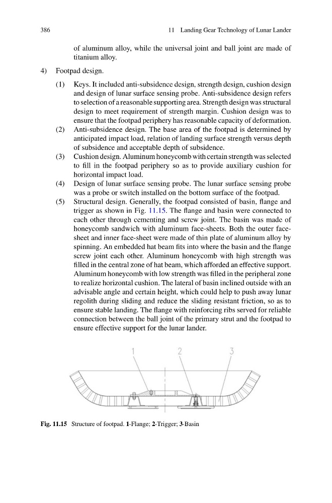
(5) Structural design. Generally, the footpad consisted of basin, flange and
trigger as shown in Fig. 11.15. The flange and basin were connected to
each other through cementing and screw joint. The basin was made of
honeycomb sandwich with aluminum face-sheets. Both the outer facesheet and inner face-sheet were made of thin plate of aluminum alloy by
spinning. An embedded hat beam fits into where the basin and the flange
screw joint each other. Aluminum honeycomb with high strength was
filled in the central zone of hat beam, which afforded an effective support.
Aluminum honeycomb with low strength was filled in the peripheral zone
to realize horizontal cushion. The lateral of basin inclined outside with an
advisable angle and certain height, which could help to push away lunar
regolith during sliding and reduce the sliding resistant friction, so as to
ensure stable landing. The flange with reinforcing ribs served for reliable
connection between the ball joint of the primary strut and the footpad to
ensure effective support for the lunar lander.
Fig. 11.15 Structure of footpad. 1-Flange; 2-Trigger; 3-Basin
11 Landing Gear Technology of Lunar Lander
of aluminum alloy, while the universal joint and ball joint are made of
titanium alloy.
4) Footpad design.
(1) Keys. It included anti-subsidence design, strength design, cushion design
and design of lunar surface sensing probe. Anti-subsidence design refers
to selection of a reasonable supporting area. Strength design was structural
design to meet requirement of strength margin. Cushion design was to
ensure that the footpad periphery has reasonable capacity of deformation.
(2) Anti-subsidence design. The base area of the footpad is determined by
anticipated impact load, relation of landing surface strength versus depth
of subsidence and acceptable depth of subsidence.
(3) Cushion design. Aluminum honeycomb with certain strength was selected
to fill in the footpad periphery so as to provide auxiliary cushion for
horizontal impact load.
(4) Design of lunar surface sensing probe. The lunar surface sensing probe
was a probe or switch installed on the bottom surface of the footpad.
(5) Structural design. Generally, the footpad consisted of basin, flange and
trigger as shown in Fig. 11.15. The flange and basin were connected to
each other through cementing and screw joint. The basin was made of
honeycomb sandwich with aluminum face-sheets. Both the outer facesheet and inner face-sheet were made of thin plate of aluminum alloy by
spinning. An embedded hat beam fits into where the basin and the flange
screw joint each other. Aluminum honeycomb with high strength was
filled in the central zone of hat beam, which afforded an effective support.
Aluminum honeycomb with low strength was filled in the peripheral zone
to realize horizontal cushion. The lateral of basin inclined outside with an
advisable angle and certain height, which could help to push away lunar
regolith during sliding and reduce the sliding resistant friction, so as to
ensure stable landing. The flange with reinforcing ribs served for reliable
connection between the ball joint of the primary strut and the footpad to
ensure effective support for the lunar lander.
Fig. 11.15 Structure of footpad. 1-Flange; 2-Trigger; 3-Basin