

384
11 Landing Gear Technology of Lunar Lander
(1) Keys. It included cushion design and strength design. The cushion design
included cushion material selection, determination of cushion force and
stroke. The strength design was to meet requirement of strength margin
by structural design.
(2) Cushion material selection. Generally, the material like aluminum honeycomb was preferred because of the stably compression process [8]. In
some special cases, stretchable wire made of super plastic material like
high manganese steel is alternative.
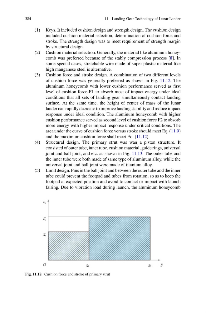
(3) Cushion force and stroke design. A combination of two different levels
of cushion force was generally preferred as shown in Fig. 11.12. The
aluminum honeycomb with lower cushion performance served as first
level of cushion force F1 to absorb most of impact energy under ideal
conditions that all sets of landing gear simultaneously contact landing
surface. At the same time, the height of center of mass of the lunar
lander can rapidly decrease to improve landing stability and reduce impact
response under ideal condition. The aluminum honeycomb with higher
cushion performance served as second level of cushion force F2 to absorb
more energy with higher impact response under critical conditions. The
area under the curve of cushion force versus stroke should meet Eq. (11.9)
and the maximum cushion force shall meet Eq. (11.12).
(4) Structural design. The primary strut was wan a piston structure. It
consisted of outer tube, inner tube, cushion material, guide rings, universal
joint and ball joint, and etc. as shown in Fig. 11.13. The outer tube and
the inner tube were both made of same type of aluminum alloy, while the
universal joint and ball joint were made of titanium alloy.
(5) Limit design. Pins in the ball joint and between the outer tube and the inner
tube could prevent the footpad and tubes from rotation, so as to keep the
footpad at expected position and avoid to contact or impact with launch
fairing. Due to vibration load during launch, the aluminum honeycomb
Fig. 11.12 Cushion force and stroke of primary strut
11 Landing Gear Technology of Lunar Lander
(1) Keys. It included cushion design and strength design. The cushion design
included cushion material selection, determination of cushion force and
stroke. The strength design was to meet requirement of strength margin
by structural design.
(2) Cushion material selection. Generally, the material like aluminum honeycomb was preferred because of the stably compression process [8]. In
some special cases, stretchable wire made of super plastic material like
high manganese steel is alternative.
(3) Cushion force and stroke design. A combination of two different levels
of cushion force was generally preferred as shown in Fig. 11.12. The
aluminum honeycomb with lower cushion performance served as first
level of cushion force F1 to absorb most of impact energy under ideal
conditions that all sets of landing gear simultaneously contact landing
surface. At the same time, the height of center of mass of the lunar
lander can rapidly decrease to improve landing stability and reduce impact
response under ideal condition. The aluminum honeycomb with higher
cushion performance served as second level of cushion force F2 to absorb
more energy with higher impact response under critical conditions. The
area under the curve of cushion force versus stroke should meet Eq. (11.9)
and the maximum cushion force shall meet Eq. (11.12).
(4) Structural design. The primary strut was wan a piston structure. It
consisted of outer tube, inner tube, cushion material, guide rings, universal
joint and ball joint, and etc. as shown in Fig. 11.13. The outer tube and
the inner tube were both made of same type of aluminum alloy, while the
universal joint and ball joint were made of titanium alloy.
(5) Limit design. Pins in the ball joint and between the outer tube and the inner
tube could prevent the footpad and tubes from rotation, so as to keep the
footpad at expected position and avoid to contact or impact with launch
fairing. Due to vibration load during launch, the aluminum honeycomb
Fig. 11.12 Cushion force and stroke of primary strut