

264
7 Guidance, Navigation and Control Technology …
6-DOF Motion
Simulation
Platform
Include 3-DOF
translation
platform and
flight rotation
simulation
platform
Laser Rangfinderr
Laser 3-D Imaging
Sensor
Mounted on the load
pan of the flight rotation
simulation platform
Optical
Terminal
Optical
Terminal
CCU
(Central Control
Unit)
Include GNC computer
and Image Processing Board,
etc
Microwave
Range and
Velocity Sensor
Range and Velocity
Target Simulator
Dynamic
Computer
Ground Test Main
Control Computer
IMU
(Gyro、Accelerometer)
Propallant subsystem
(7500N Variable Thrust
Engine、150N and 10N
thrustors)
Gama Shutdown
Sesor
Sensor and Actuator
Interface Box
Data
display
computer
1
Data
display
computer
n
Visualization
Image Station
Data
display
computer
2
Large Screen and
High-definition
Projector
Initialization
Dynamic
Parameters
Range、Image
Range
Velocity
Fiber
Digital Simulation Demonstration Platform
Testing
Hall
Telecontrol
Hall
……
Motion Smulation
System
Located on the
Ground
Reflective
Memory
Reflective Memory
High Speed Ethernet
Software
Uploading
RS422
0/5V
Voltage
RS422
OC Output
RS422
LVDS
RS422
RS422
Satellite and Rocket
Separation Signal
CCU Reset Signal
0/5V
Voltage
0/5V
Voltage
GNC Monitoring
Computer
RS422
Telemetry
Data
Sand Model
(lunar surface
simulation, laser &
optical reflection
characteristics,etc)
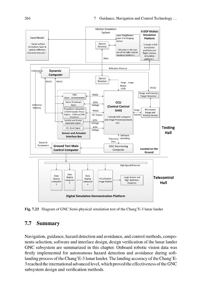
Fig. 7.23 Diagram of GNC Semi-physical simulation test of the Chang’E-3 lunar lander
7.7 Summary
Navigation, guidance, hazard detection and avoidance, and control methods, components selection, software and interface design, design verification of the lunar lander
GNC subsystem are summarized in this chapter. Onboard robotic vision data was
firstly implemented for autonomous hazard detection and avoidance during softlanding process of the Chang’E-3 lunar lander. The landing accuracy of the Chang’E3 reached the international advanced level, which proved the effectiveness of the GNC
subsystem design and verification methods.
7 Guidance, Navigation and Control Technology …
6-DOF Motion
Simulation
Platform
Include 3-DOF
translation
platform and
flight rotation
simulation
platform
Laser Rangfinderr
Laser 3-D Imaging
Sensor
Mounted on the load
pan of the flight rotation
simulation platform
Optical
Terminal
Optical
Terminal
CCU
(Central Control
Unit)
Include GNC computer
and Image Processing Board,
etc
Microwave
Range and
Velocity Sensor
Range and Velocity
Target Simulator
Dynamic
Computer
Ground Test Main
Control Computer
IMU
(Gyro、Accelerometer)
Propallant subsystem
(7500N Variable Thrust
Engine、150N and 10N
thrustors)
Gama Shutdown
Sesor
Sensor and Actuator
Interface Box
Data
display
computer
1
Data
display
computer
n
Visualization
Image Station
Data
display
computer
2
Large Screen and
High-definition
Projector
Initialization
Dynamic
Parameters
Range、Image
Range
Velocity
Fiber
Digital Simulation Demonstration Platform
Testing
Hall
Telecontrol
Hall
……
Motion Smulation
System
Located on the
Ground
Reflective
Memory
Reflective Memory
High Speed Ethernet
Software
Uploading
RS422
0/5V
Voltage
RS422
OC Output
RS422
LVDS
RS422
RS422
Satellite and Rocket
Separation Signal
CCU Reset Signal
0/5V
Voltage
0/5V
Voltage
GNC Monitoring
Computer
RS422
Telemetry
Data
Sand Model
(lunar surface
simulation, laser &
optical reflection
characteristics,etc)
Fig. 7.23 Diagram of GNC Semi-physical simulation test of the Chang’E-3 lunar lander
7.7 Summary
Navigation, guidance, hazard detection and avoidance, and control methods, components selection, software and interface design, design verification of the lunar lander
GNC subsystem are summarized in this chapter. Onboard robotic vision data was
firstly implemented for autonomous hazard detection and avoidance during softlanding process of the Chang’E-3 lunar lander. The landing accuracy of the Chang’E3 reached the international advanced level, which proved the effectiveness of the GNC
subsystem design and verification methods.