

7.5 Typical Technology
257
Fig. 7.15 Partition control
strategy
Angle and angular
velocity
control
area
dθ r
dθ
θ
θ m
Nominal angular
velocity control
area
-θ m
-dθ r
Nominal angular
velocity control
area
Fig. 7.16 Block diagram of
PID/PI + PWM attitude
control system of the
Chang’E-3 lunar lander
PID/PI
Guidance
Target
PWM
Thrustors
CE-3
Lander
Disturbance
Sensors
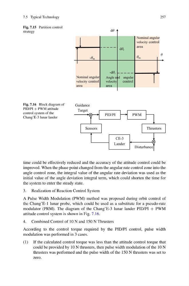
time could be effectively reduced and the accuracy of the attitude control could be
improved. When the phase point changed from the angular rate control zone into the
angle control zone, the integral value of the angular rate deviation was used as the
initial value of the angle deviation integral term, which could shorten the time for
the system to enter the steady state.
3. Realization of Reaction Control System
A Pulse Width Modulation (PWM) method was proposed during orbit control of
the Chang’E-1 lunar probe, which could be used as a substitute for a pseudo-rate
modulator (PRM). The diagram of the Chang’E-3 lunar lander PID/PI + PWM
attitude control system is shown in Fig. 7.16.
4. Combined Control of 10 N and 150 N Thrusters
According to the control torque required by the PID/PI control, pulse width
modulation was performed in 3 cases.
(1) If the calculated control torque was less than the attitude control torque that
could be provided by 10 N thrusters, then pulse width modulation of the 10 N
thrusters was performed and the pulse width of the 150 N thrusters was set to
zero.
257
Fig. 7.15 Partition control
strategy
Angle and angular
velocity
control
area
dθ r
dθ
θ
θ m
Nominal angular
velocity control
area
-θ m
-dθ r
Nominal angular
velocity control
area
Fig. 7.16 Block diagram of
PID/PI + PWM attitude
control system of the
Chang’E-3 lunar lander
PID/PI
Guidance
Target
PWM
Thrustors
CE-3
Lander
Disturbance
Sensors
time could be effectively reduced and the accuracy of the attitude control could be
improved. When the phase point changed from the angular rate control zone into the
angle control zone, the integral value of the angular rate deviation was used as the
initial value of the angle deviation integral term, which could shorten the time for
the system to enter the steady state.
3. Realization of Reaction Control System
A Pulse Width Modulation (PWM) method was proposed during orbit control of
the Chang’E-1 lunar probe, which could be used as a substitute for a pseudo-rate
modulator (PRM). The diagram of the Chang’E-3 lunar lander PID/PI + PWM
attitude control system is shown in Fig. 7.16.
4. Combined Control of 10 N and 150 N Thrusters
According to the control torque required by the PID/PI control, pulse width
modulation was performed in 3 cases.
(1) If the calculated control torque was less than the attitude control torque that
could be provided by 10 N thrusters, then pulse width modulation of the 10 N
thrusters was performed and the pulse width of the 150 N thrusters was set to
zero.