

246
7 Guidance, Navigation and Control Technology …
Control
Force and
Moment
Navigation
Algorithm
Attitude, Position,
Velocity and
Thruster
Acceleration
Attitude
Command
Attitude Angular Increment,
Velocity Increment Pulses,
Slant Range and Line of Sight
Velocity along Wave Beam
Guidance
Law
Attitude
Control
Navigation Sensor
IMU+RVS
Lander Dynamics
Model and Lunar
Surface Model, etc
Actuator
(Engine+Thrusters)
Inertial Attitude
Image Process
Board
GNC
Computer
Lunar Surface Hazard
Detection and Safe Landing
Area Selection
Optical Image Sensor
and 3-D Laser Image
Sensor
Thrusters
Command
Main Engine
Command
Controller
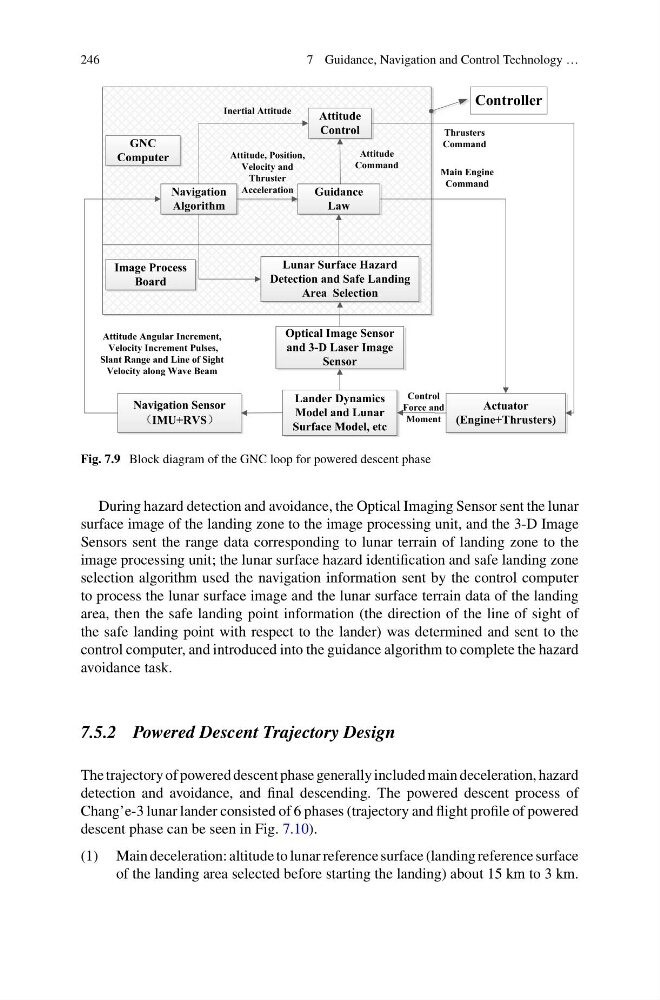
Fig. 7.9 Block diagram of the GNC loop for powered descent phase
During hazard detection and avoidance, the Optical Imaging Sensor sent the lunar
surface image of the landing zone to the image processing unit, and the 3-D Image
Sensors sent the range data corresponding to lunar terrain of landing zone to the
image processing unit; the lunar surface hazard identification and safe landing zone
selection algorithm used the navigation information sent by the control computer
to process the lunar surface image and the lunar surface terrain data of the landing
area, then the safe landing point information (the direction of the line of sight of
the safe landing point with respect to the lander) was determined and sent to the
control computer, and introduced into the guidance algorithm to complete the hazard
avoidance task.
7.5.2 Powered Descent Trajectory Design
The trajectory of powered descent phase generally included main deceleration, hazard
detection and avoidance, and final descending. The powered descent process of
Chang’e-3 lunar lander consisted of 6 phases (trajectory and flight profile of powered
descent phase can be seen in Fig. 7.10).
(1) Main deceleration: altitude to lunar reference surface (landing reference surface
of the landing area selected before starting the landing) about 15 km to 3 km.
7 Guidance, Navigation and Control Technology …
Control
Force and
Moment
Navigation
Algorithm
Attitude, Position,
Velocity and
Thruster
Acceleration
Attitude
Command
Attitude Angular Increment,
Velocity Increment Pulses,
Slant Range and Line of Sight
Velocity along Wave Beam
Guidance
Law
Attitude
Control
Navigation Sensor
IMU+RVS
Lander Dynamics
Model and Lunar
Surface Model, etc
Actuator
(Engine+Thrusters)
Inertial Attitude
Image Process
Board
GNC
Computer
Lunar Surface Hazard
Detection and Safe Landing
Area Selection
Optical Image Sensor
and 3-D Laser Image
Sensor
Thrusters
Command
Main Engine
Command
Controller
Fig. 7.9 Block diagram of the GNC loop for powered descent phase
During hazard detection and avoidance, the Optical Imaging Sensor sent the lunar
surface image of the landing zone to the image processing unit, and the 3-D Image
Sensors sent the range data corresponding to lunar terrain of landing zone to the
image processing unit; the lunar surface hazard identification and safe landing zone
selection algorithm used the navigation information sent by the control computer
to process the lunar surface image and the lunar surface terrain data of the landing
area, then the safe landing point information (the direction of the line of sight of
the safe landing point with respect to the lander) was determined and sent to the
control computer, and introduced into the guidance algorithm to complete the hazard
avoidance task.
7.5.2 Powered Descent Trajectory Design
The trajectory of powered descent phase generally included main deceleration, hazard
detection and avoidance, and final descending. The powered descent process of
Chang’e-3 lunar lander consisted of 6 phases (trajectory and flight profile of powered
descent phase can be seen in Fig. 7.10).
(1) Main deceleration: altitude to lunar reference surface (landing reference surface
of the landing area selected before starting the landing) about 15 km to 3 km.