

4.3 Design and Verification of Lunar Lander Structure
117
(3) Angle bar for structure connection was simulated by plate element.
(4) Bond between angle bar and structural panels was simulated by element
common nodes, and the Multi Point Constraint (MPC) method was used to
simulate the screw connection.
(5) Boundary condition is simple support by the far boundary, and the load was
applied at the connection point of main pillar of landing cushion mechanisms.
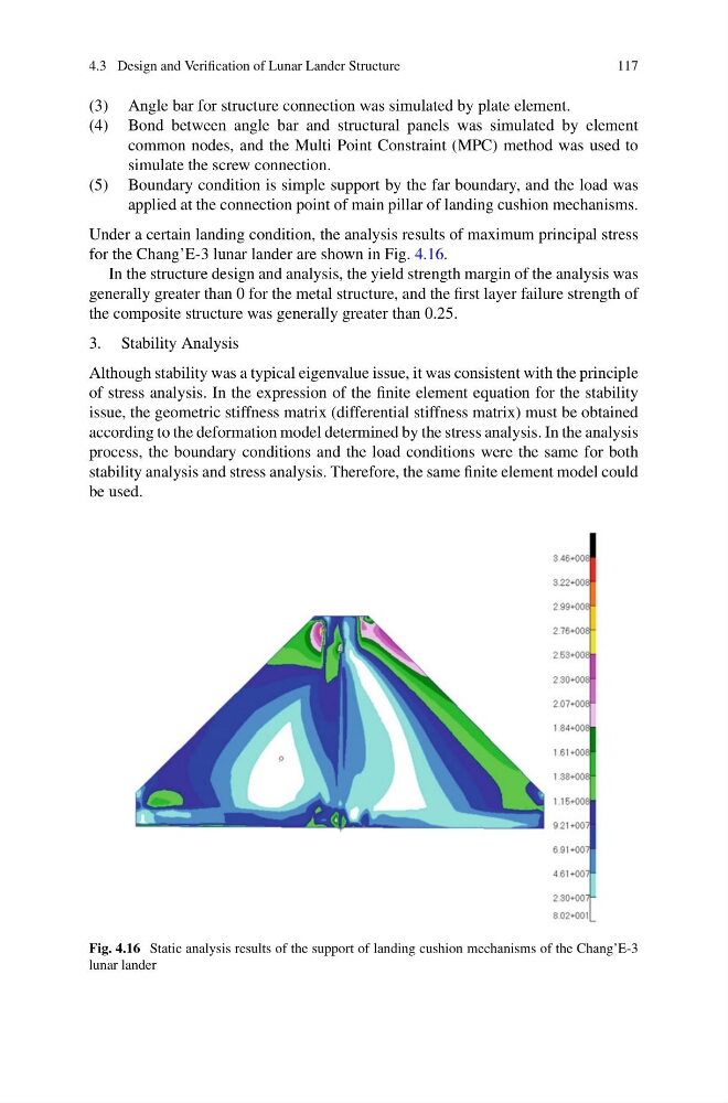
Under a certain landing condition, the analysis results of maximum principal stress
for the Chang’E-3 lunar lander are shown in Fig. 4.16.
In the structure design and analysis, the yield strength margin of the analysis was
generally greater than 0 for the metal structure, and the first layer failure strength of
the composite structure was generally greater than 0.25.
3. Stability Analysis
Although stability was a typical eigenvalue issue, it was consistent with the principle
of stress analysis. In the expression of the finite element equation for the stability
issue, the geometric stiffness matrix (differential stiffness matrix) must be obtained
according to the deformation model determined by the stress analysis. In the analysis
process, the boundary conditions and the load conditions were the same for both
stability analysis and stress analysis. Therefore, the same finite element model could
be used.
Fig. 4.16 Static analysis results of the support of landing cushion mechanisms of the Chang’E-3
lunar lander
117
(3) Angle bar for structure connection was simulated by plate element.
(4) Bond between angle bar and structural panels was simulated by element
common nodes, and the Multi Point Constraint (MPC) method was used to
simulate the screw connection.
(5) Boundary condition is simple support by the far boundary, and the load was
applied at the connection point of main pillar of landing cushion mechanisms.
Under a certain landing condition, the analysis results of maximum principal stress
for the Chang’E-3 lunar lander are shown in Fig. 4.16.
In the structure design and analysis, the yield strength margin of the analysis was
generally greater than 0 for the metal structure, and the first layer failure strength of
the composite structure was generally greater than 0.25.
3. Stability Analysis
Although stability was a typical eigenvalue issue, it was consistent with the principle
of stress analysis. In the expression of the finite element equation for the stability
issue, the geometric stiffness matrix (differential stiffness matrix) must be obtained
according to the deformation model determined by the stress analysis. In the analysis
process, the boundary conditions and the load conditions were the same for both
stability analysis and stress analysis. Therefore, the same finite element model could
be used.
Fig. 4.16 Static analysis results of the support of landing cushion mechanisms of the Chang’E-3
lunar lander