

4.3 Design and Verification of Lunar Lander Structure
111
(2) Longitudinal load: Longitudinal load of the fuel tanks (in this case, the propellant was almost exhausted and the load was small) was transferred to the
cross-support structure through the interface ring, and the longitudinal load of
other equipment was directly transferred to the cross-support structure. The
load on the cross-support structure was transferred to main pillars of landing
cushion mechanisms through the support of landing gears, and finally to lunar
surface.
From above analysis, it implied that the cross baffles and the support of landing gears
was the primary bearing components of the structure for landing impact load. Special
attention should be paid to the mechanics design of such structure.
4. Structural Component Design
The structural components design could be started after configuration design was
finished. The factors in structural components design included: strength, stiffness, mechanical interface (including accuracy), assembly requirements, functional requirements (such as heat dissipation, conductive insulation, etc.), and
manufacturing processes.
After the material and basic shape of the structural components was determined,
the cross section size and thickness should be determined through mechanical analysis. For the design of the component connection point, especially the primary
force transfer point, the load was generally given through mechanical analysis. The
specific form of the connection point sometimes should be determined after local
tests verification (the local structure static test was generally required due to the
boundary).
A brief description of the structural design method is given as following for the
cross support structure of the Chang’E-3 lunar lander as an example.
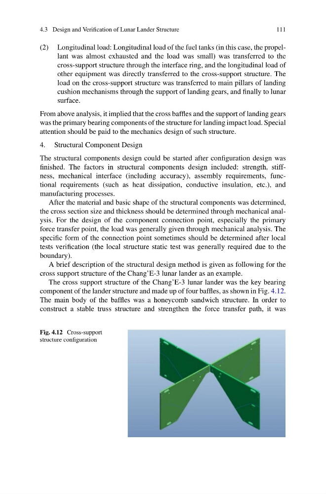
The cross support structure of the Chang’E-3 lunar lander was the key bearing
component of the lander structure and made up of four baffles, as shown in Fig. 4.12.
The main body of the baffles was a honeycomb sandwich structure. In order to
construct a stable truss structure and strengthen the force transfer path, it was
Fig. 4.12 Cross-support
structure configuration
111
(2) Longitudinal load: Longitudinal load of the fuel tanks (in this case, the propellant was almost exhausted and the load was small) was transferred to the
cross-support structure through the interface ring, and the longitudinal load of
other equipment was directly transferred to the cross-support structure. The
load on the cross-support structure was transferred to main pillars of landing
cushion mechanisms through the support of landing gears, and finally to lunar
surface.
From above analysis, it implied that the cross baffles and the support of landing gears
was the primary bearing components of the structure for landing impact load. Special
attention should be paid to the mechanics design of such structure.
4. Structural Component Design
The structural components design could be started after configuration design was
finished. The factors in structural components design included: strength, stiffness, mechanical interface (including accuracy), assembly requirements, functional requirements (such as heat dissipation, conductive insulation, etc.), and
manufacturing processes.
After the material and basic shape of the structural components was determined,
the cross section size and thickness should be determined through mechanical analysis. For the design of the component connection point, especially the primary
force transfer point, the load was generally given through mechanical analysis. The
specific form of the connection point sometimes should be determined after local
tests verification (the local structure static test was generally required due to the
boundary).
A brief description of the structural design method is given as following for the
cross support structure of the Chang’E-3 lunar lander as an example.
The cross support structure of the Chang’E-3 lunar lander was the key bearing
component of the lander structure and made up of four baffles, as shown in Fig. 4.12.
The main body of the baffles was a honeycomb sandwich structure. In order to
construct a stable truss structure and strengthen the force transfer path, it was
Fig. 4.12 Cross-support
structure configuration