

94
3 System Design of Lunar Lander
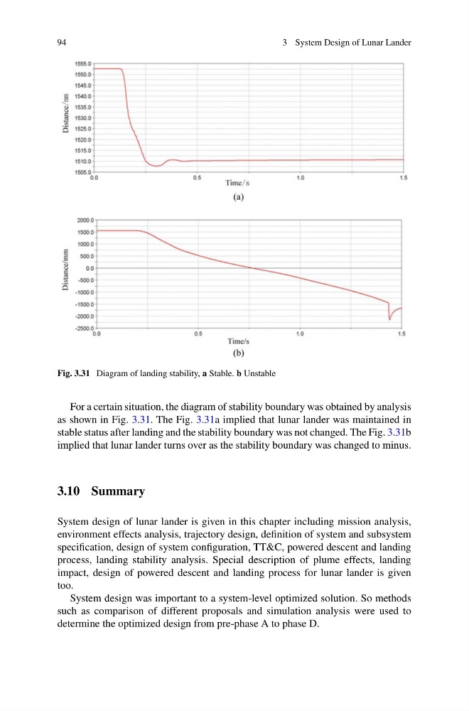
Fig. 3.31 Diagram of landing stability, a Stable. b Unstable
For a certain situation, the diagram of stability boundary was obtained by analysis
as shown in Fig. 3.31. The Fig. 3.31a implied that lunar lander was maintained in
stable status after landing and the stability boundary was not changed. The Fig. 3.31b
implied that lunar lander turns over as the stability boundary was changed to minus.
3.10 Summary
System design of lunar lander is given in this chapter including mission analysis,
environment effects analysis, trajectory design, definition of system and subsystem
specification, design of system configuration, TT&C, powered descent and landing
process, landing stability analysis. Special description of plume effects, landing
impact, design of powered descent and landing process for lunar lander is given
too.
System design was important to a system-level optimized solution. So methods
such as comparison of different proposals and simulation analysis were used to
determine the optimized design from pre-phase A to phase D.
3 System Design of Lunar Lander
Fig. 3.31 Diagram of landing stability, a Stable. b Unstable
For a certain situation, the diagram of stability boundary was obtained by analysis
as shown in Fig. 3.31. The Fig. 3.31a implied that lunar lander was maintained in
stable status after landing and the stability boundary was not changed. The Fig. 3.31b
implied that lunar lander turns over as the stability boundary was changed to minus.
3.10 Summary
System design of lunar lander is given in this chapter including mission analysis,
environment effects analysis, trajectory design, definition of system and subsystem
specification, design of system configuration, TT&C, powered descent and landing
process, landing stability analysis. Special description of plume effects, landing
impact, design of powered descent and landing process for lunar lander is given
too.
System design was important to a system-level optimized solution. So methods
such as comparison of different proposals and simulation analysis were used to
determine the optimized design from pre-phase A to phase D.