

18 Fault Isolation and Failure Analysis of 3D Packaging
595
18.3.2.3 2D X-Ray Radiography
2D X-ray radiography has been widely used in the semiconductor industry to inspect
solder joint defects in packages. Samples are put between the punctiform X-ray
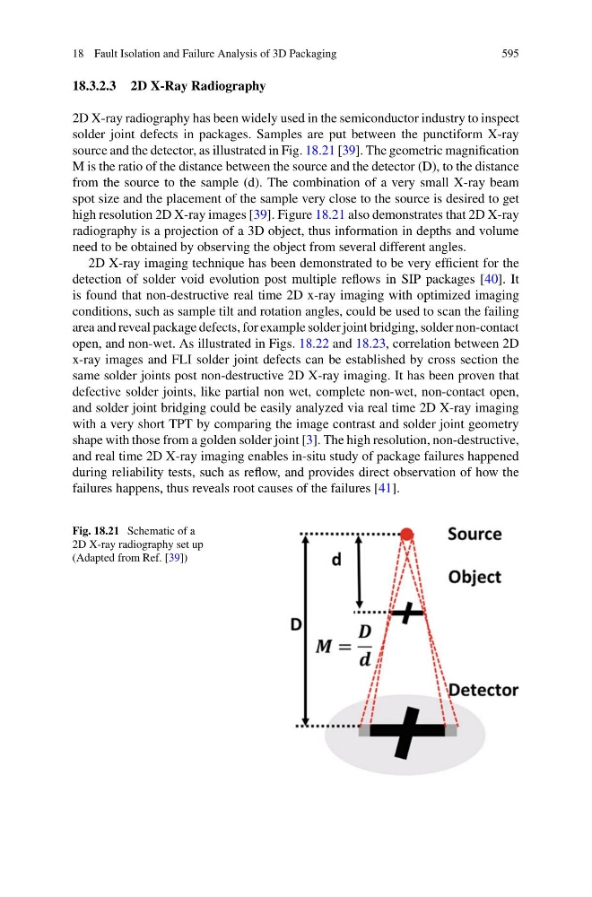
source and the detector, as illustrated in Fig. 18.21 [39]. The geometric magnification
M is the ratio of the distance between the source and the detector (D), to the distance
from the source to the sample (d). The combination of a very small X-ray beam
spot size and the placement of the sample very close to the source is desired to get
high resolution 2D X-ray images [39]. Figure 18.21 also demonstrates that 2D X-ray
radiography is a projection of a 3D object, thus information in depths and volume
need to be obtained by observing the object from several different angles.
2D X-ray imaging technique has been demonstrated to be very efficient for the
detection of solder void evolution post multiple reflows in SIP packages [40]. It
is found that non-destructive real time 2D x-ray imaging with optimized imaging
conditions, such as sample tilt and rotation angles, could be used to scan the failing
area and reveal package defects, for example solder joint bridging, solder non-contact
open, and non-wet. As illustrated in Figs. 18.22 and 18.23, correlation between 2D
x-ray images and FLI solder joint defects can be established by cross section the
same solder joints post non-destructive 2D X-ray imaging. It has been proven that
defective solder joints, like partial non wet, complete non-wet, non-contact open,
and solder joint bridging could be easily analyzed via real time 2D X-ray imaging
with a very short TPT by comparing the image contrast and solder joint geometry
shape with those from a golden solder joint [3]. The high resolution, non-destructive,
and real time 2D X-ray imaging enables in-situ study of package failures happened
during reliability tests, such as reflow, and provides direct observation of how the
failures happens, thus reveals root causes of the failures [41].
Fig. 18.21 Schematic of a
2D X-ray radiography set up
(Adapted from Ref. [39])