

580
Y. Li and D. Goyal
By adding more reference spectra to define the locations of the multiple levels of
solder interconnects in 3D packages, TDR has been demonstrated to be quite effective
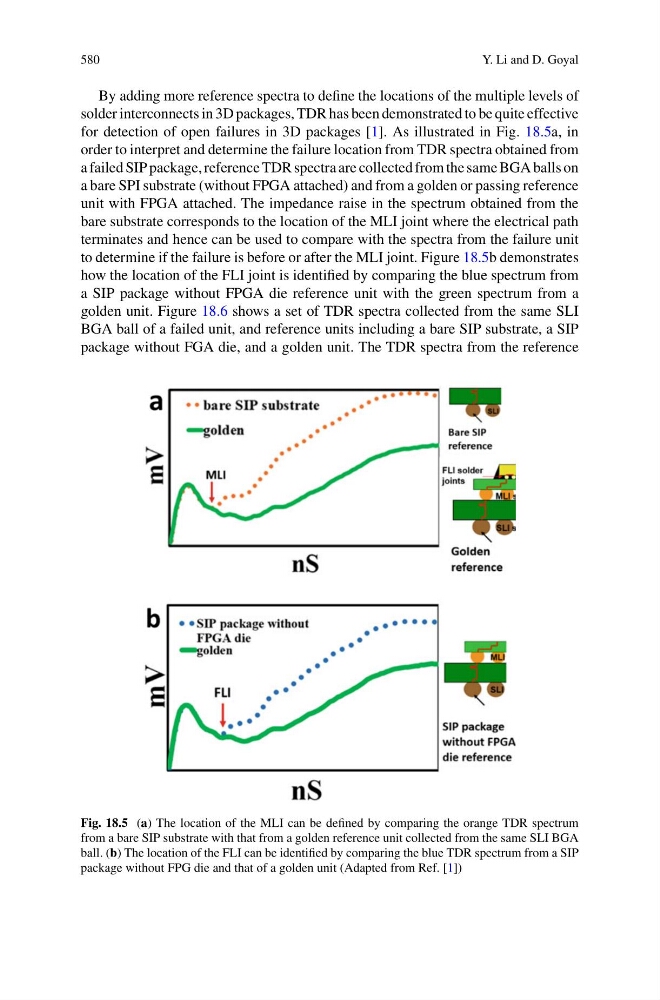
for detection of open failures in 3D packages [1]. As illustrated in Fig. 18.5a, in
order to interpret and determine the failure location from TDR spectra obtained from
a failed SIP package, reference TDR spectra are collected from the same BGA balls on
a bare SPI substrate (without FPGA attached) and from a golden or passing reference
unit with FPGA attached. The impedance raise in the spectrum obtained from the
bare substrate corresponds to the location of the MLI joint where the electrical path
terminates and hence can be used to compare with the spectra from the failure unit
to determine if the failure is before or after the MLI joint. Figure 18.5b demonstrates
how the location of the FLI joint is identified by comparing the blue spectrum from
a SIP package without FPGA die reference unit with the green spectrum from a
golden unit. Figure 18.6 shows a set of TDR spectra collected from the same SLI
BGA ball of a failed unit, and reference units including a bare SIP substrate, a SIP
package without FGA die, and a golden unit. The TDR spectra from the reference
Fig. 18.5 (a) The location of the MLI can be defined by comparing the orange TDR spectrum
from a bare SIP substrate with that from a golden reference unit collected from the same SLI BGA
ball. (b) The location of the FLI can be identified by comparing the blue TDR spectrum from a SIP
package without FPG die and that of a golden unit (Adapted from Ref. [1])
Y. Li and D. Goyal
By adding more reference spectra to define the locations of the multiple levels of
solder interconnects in 3D packages, TDR has been demonstrated to be quite effective
for detection of open failures in 3D packages [1]. As illustrated in Fig. 18.5a, in
order to interpret and determine the failure location from TDR spectra obtained from
a failed SIP package, reference TDR spectra are collected from the same BGA balls on
a bare SPI substrate (without FPGA attached) and from a golden or passing reference
unit with FPGA attached. The impedance raise in the spectrum obtained from the
bare substrate corresponds to the location of the MLI joint where the electrical path
terminates and hence can be used to compare with the spectra from the failure unit
to determine if the failure is before or after the MLI joint. Figure 18.5b demonstrates
how the location of the FLI joint is identified by comparing the blue spectrum from
a SIP package without FPGA die reference unit with the green spectrum from a
golden unit. Figure 18.6 shows a set of TDR spectra collected from the same SLI
BGA ball of a failed unit, and reference units including a bare SIP substrate, a SIP
package without FGA die, and a golden unit. The TDR spectra from the reference
Fig. 18.5 (a) The location of the MLI can be defined by comparing the orange TDR spectrum
from a bare SIP substrate with that from a golden reference unit collected from the same SLI BGA
ball. (b) The location of the FLI can be identified by comparing the blue TDR spectrum from a SIP
package without FPG die and that of a golden unit (Adapted from Ref. [1])