

16 Processing and Reliability of Solder Interconnections …
511
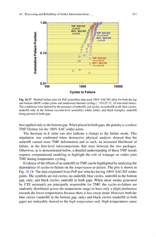
Fig. 16.17 Weibull failure plot for PoP assemblies that used 100% SAC305 alloy for both the top
and bottom (BOT) solder joints and underwent thermal cycling (−55/125 °C; 10 min hold times).
The conditions were defined by the presence of underfill: red circles, no underfill at all; blue circles,
underfill only in the bottom (second-level assembly) solder joints; and black triangles, underfill
being present in both gaps
best applied only to the bottom gap. When placed in both gaps, the penalty is a reduce
TMF lifetime for the 100% SAC solder joints.
The decrease in β value can also indicate a change to the failure mode. This
stipulation was confirmed when destructive physical analysis showed that the
underfill caused more TMF deformation and as such, an increased likelihood of
failure, in the first-level interconnections that were between the two packages.
Otherwise, as is demonstrated below, a detailed understanding of these TMF trends
requires computational modeling to highlight the role of warpage on solder joint
TMF during temperature cycling.
Evidence of the effects of an underfill on TMF can be highlighted by analyzing the
dependence of cycles-to-failure on the temperature-at-failure. The plot is shown in
Fig. 16.18. The data originated from PoP test vehicles having 100% SAC305 solder
joints. The symbols are red circles, no underfill; blue circles, underfill in the bottom
gap, only; and black circles, underfill in both gaps. When shear strains generated
by CTE mismatch are principally responsible for TMF, the cycles-to-failure are
randomly distributed across the temperature range or have only a slight preference
towards the lower temperatures because there is less creep strain. However, both the
blue circles (underfill in the bottom gap, only) and black circles (underfill in both
gaps) are noticeably skewed to the high temperature end. High temperatures cause
511
Fig. 16.17 Weibull failure plot for PoP assemblies that used 100% SAC305 alloy for both the top
and bottom (BOT) solder joints and underwent thermal cycling (−55/125 °C; 10 min hold times).
The conditions were defined by the presence of underfill: red circles, no underfill at all; blue circles,
underfill only in the bottom (second-level assembly) solder joints; and black triangles, underfill
being present in both gaps
best applied only to the bottom gap. When placed in both gaps, the penalty is a reduce
TMF lifetime for the 100% SAC solder joints.
The decrease in β value can also indicate a change to the failure mode. This
stipulation was confirmed when destructive physical analysis showed that the
underfill caused more TMF deformation and as such, an increased likelihood of
failure, in the first-level interconnections that were between the two packages.
Otherwise, as is demonstrated below, a detailed understanding of these TMF trends
requires computational modeling to highlight the role of warpage on solder joint
TMF during temperature cycling.
Evidence of the effects of an underfill on TMF can be highlighted by analyzing the
dependence of cycles-to-failure on the temperature-at-failure. The plot is shown in
Fig. 16.18. The data originated from PoP test vehicles having 100% SAC305 solder
joints. The symbols are red circles, no underfill; blue circles, underfill in the bottom
gap, only; and black circles, underfill in both gaps. When shear strains generated
by CTE mismatch are principally responsible for TMF, the cycles-to-failure are
randomly distributed across the temperature range or have only a slight preference
towards the lower temperatures because there is less creep strain. However, both the
blue circles (underfill in the bottom gap, only) and black circles (underfill in both
gaps) are noticeably skewed to the high temperature end. High temperatures cause