

16 Processing and Reliability of Solder Interconnections …
485
16.2.4 Inspection Techniques
The post-assembly inspection of PoP and PoPoP components on a PWA is generally
not unlike that of BGA components. The acceptance criteria are applied to both firstlevel and second-level interconnections. The same defects are observed on stacked
packages: damaged to the molding compound and/or substrate (interposer); missing
solder balls; open solder joints; and solder joint bridges that lead to short-circuits.
The inspection methods are also the same as those used for area-array packages.
A visual inspection can be made of the perimeter joints. A boroscope can be used
to examine the internal connections. However, the latter method may have limited
application with PoP and PoPoP first- and second-level interconnections because the
fine pitches limit the space around the solder joints in which to maneuver the light
source and camera.
X-ray inspection provides the means to examine the internal interconnections.
However, there is additional complexity of the images due to the multiple rows of
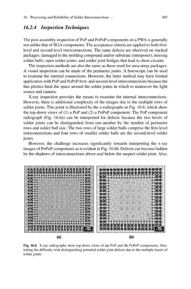
solder joints. This point is illustrated by the x-radiographs in Fig. 16.6, which show
the top-down views of (1) a PoP and (2) a PoPoP component. The PoP component
radiograph (Fig. 16.6a) can be interpreted for defects because the two levels of
solder joints can be distinguished from one-another by the number of perimeter
rows and solder ball size. The two rows of large solder balls comprise the first-level
interconnections and four rows of smaller solder balls are the second-level solder
joints.
However, the challenge increases significantly towards interpreting the x-ray
images of PoPoP components as is evident in Fig. 16.6b. Defects can become hidden
by the shadows of interconnections above and below the suspect solder joint. Also,
Fig. 16.6 X-ray radiographs show top-down views of (a) PoP and (b) PoPoP components, illustrating the difficulty with distinguishing potential solder joint defects due to the multiple layers of
solder joints
485
16.2.4 Inspection Techniques
The post-assembly inspection of PoP and PoPoP components on a PWA is generally
not unlike that of BGA components. The acceptance criteria are applied to both firstlevel and second-level interconnections. The same defects are observed on stacked
packages: damaged to the molding compound and/or substrate (interposer); missing
solder balls; open solder joints; and solder joint bridges that lead to short-circuits.
The inspection methods are also the same as those used for area-array packages.
A visual inspection can be made of the perimeter joints. A boroscope can be used
to examine the internal connections. However, the latter method may have limited
application with PoP and PoPoP first- and second-level interconnections because the
fine pitches limit the space around the solder joints in which to maneuver the light
source and camera.
X-ray inspection provides the means to examine the internal interconnections.
However, there is additional complexity of the images due to the multiple rows of
solder joints. This point is illustrated by the x-radiographs in Fig. 16.6, which show
the top-down views of (1) a PoP and (2) a PoPoP component. The PoP component
radiograph (Fig. 16.6a) can be interpreted for defects because the two levels of
solder joints can be distinguished from one-another by the number of perimeter
rows and solder ball size. The two rows of large solder balls comprise the first-level
interconnections and four rows of smaller solder balls are the second-level solder
joints.
However, the challenge increases significantly towards interpreting the x-ray
images of PoPoP components as is evident in Fig. 16.6b. Defects can become hidden
by the shadows of interconnections above and below the suspect solder joint. Also,
Fig. 16.6 X-ray radiographs show top-down views of (a) PoP and (b) PoPoP components, illustrating the difficulty with distinguishing potential solder joint defects due to the multiple layers of
solder joints