

15 Die and Package Level Thermal and Thermal/Moisture Stresses …
445
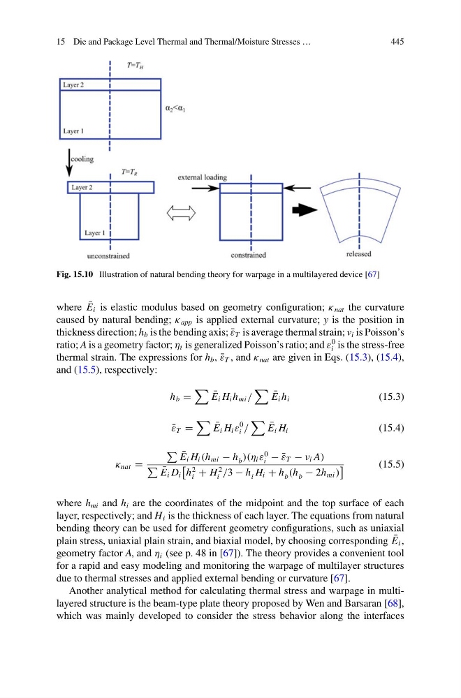
Fig. 15.10 Illustration of natural bending theory for warpage in a multilayered device [67]
where ¯
E i is elastic modulus based on geometry configuration; κ nat the curvature
caused by natural bending; κ app is applied external curvature; y is the position in
thickness direction; h b is the bending axis; ¯
ε T is average thermal strain; v i is Poisson’s
ratio; A is a geometry factor; η i is generalized Poisson’s ratio; and ε
0
i is the stress-free
thermal strain. The expressions for h b , ¯
ε T , and κ nat are given in Eqs. (15.3), (15.4),
and (15.5), respectively:
h b =
¯
E i H i h mi /
¯
E i h i
(15.3)
¯
ε T =
¯
E i H i ε
0
i /
¯
E i H i
(15.4)
κ nat =
¯
E i H i (h mi − h b )(η i ε
0
i − ¯
ε T − ν i A)
¯
E i D i
h
2
i + H
2
i /3 − h i H i + h b (h b − 2h mi )
(15.5)
where h mi and h i are the coordinates of the midpoint and the top surface of each
layer, respectively; and H i is the thickness of each layer. The equations from natural
bending theory can be used for different geometry configurations, such as uniaxial
plain stress, uniaxial plain strain, and biaxial model, by choosing corresponding ¯
E i ,
geometry factor A, and η i (see p. 48 in [67]). The theory provides a convenient tool
for a rapid and easy modeling and monitoring the warpage of multilayer structures
due to thermal stresses and applied external bending or curvature [67].
Another analytical method for calculating thermal stress and warpage in multilayered structure is the beam-type plate theory proposed by Wen and Barsaran [68],
which was mainly developed to consider the stress behavior along the interfaces
445
Fig. 15.10 Illustration of natural bending theory for warpage in a multilayered device [67]
where ¯
E i is elastic modulus based on geometry configuration; κ nat the curvature
caused by natural bending; κ app is applied external curvature; y is the position in
thickness direction; h b is the bending axis; ¯
ε T is average thermal strain; v i is Poisson’s
ratio; A is a geometry factor; η i is generalized Poisson’s ratio; and ε
0
i is the stress-free
thermal strain. The expressions for h b , ¯
ε T , and κ nat are given in Eqs. (15.3), (15.4),
and (15.5), respectively:
h b =
¯
E i H i h mi /
¯
E i h i
(15.3)
¯
ε T =
¯
E i H i ε
0
i /
¯
E i H i
(15.4)
κ nat =
¯
E i H i (h mi − h b )(η i ε
0
i − ¯
ε T − ν i A)
¯
E i D i
h
2
i + H
2
i /3 − h i H i + h b (h b − 2h mi )
(15.5)
where h mi and h i are the coordinates of the midpoint and the top surface of each
layer, respectively; and H i is the thickness of each layer. The equations from natural
bending theory can be used for different geometry configurations, such as uniaxial
plain stress, uniaxial plain strain, and biaxial model, by choosing corresponding ¯
E i ,
geometry factor A, and η i (see p. 48 in [67]). The theory provides a convenient tool
for a rapid and easy modeling and monitoring the warpage of multilayer structures
due to thermal stresses and applied external bending or curvature [67].
Another analytical method for calculating thermal stress and warpage in multilayered structure is the beam-type plate theory proposed by Wen and Barsaran [68],
which was mainly developed to consider the stress behavior along the interfaces