

374
S. G. Kandlikar and A. Ganguly
the jets used in impingement cooling, the fabrication issues still remain because of
the complex liquid distribution network required in 3D ICs. Additionally, the vapor
generated needs to be transported back to a condenser and resulting two-phase flow
due to condensation in the return lines may pose some instability concerns. A recent
review of spray cooling techniques provides an in-depth information about different
spray cooling techniques and their performance comparisons [11]. These systems
require higher pressures (from 100 to 300 kPa) and spray nozzle plates that require
periodic maintenance. This precludes their applicability to electronics cooling where
a high degree of reliability and simplicity in cooling system configuration are important. The small passage dimensions in the 3DICs also present challenges for spray
cooling systems.
13.5 Microchannel Cooling
Microchannels are generally classified as channels with their minimum dimension
in the range of 10–200 µm [12]. The microchannels are either etched directly into
the silicon substrate or etched or machined in a separate silicon or copper chip that is
bonded on the back side of the IC chip in case of conduction cooling. These passages
can also be etched between the interlayers in 3DICs.
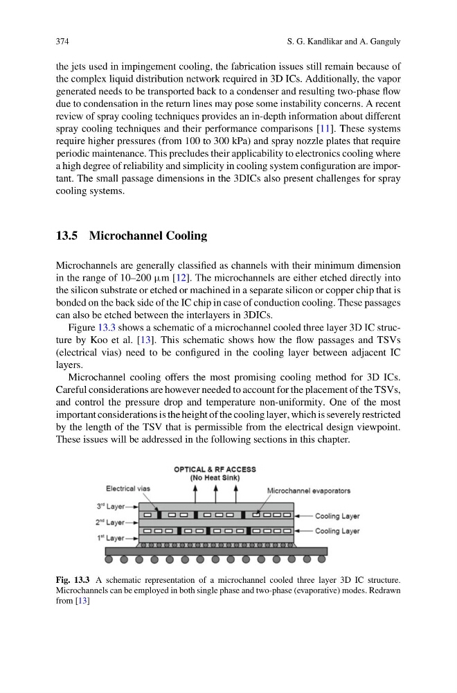
Figure 13.3 shows a schematic of a microchannel cooled three layer 3D IC structure by Koo et al. [13]. This schematic shows how the flow passages and TSVs
(electrical vias) need to be configured in the cooling layer between adjacent IC
layers.
Microchannel cooling offers the most promising cooling method for 3D ICs.
Careful considerations are however needed to account for the placement of the TSVs,
and control the pressure drop and temperature non-uniformity. One of the most
important considerations is the height of the cooling layer, which is severely restricted
by the length of the TSV that is permissible from the electrical design viewpoint.
These issues will be addressed in the following sections in this chapter.
Fig. 13.3 A schematic representation of a microchannel cooled three layer 3D IC structure.
Microchannels can be employed in both single phase and two-phase (evaporative) modes. Redrawn
from [13]
S. G. Kandlikar and A. Ganguly
the jets used in impingement cooling, the fabrication issues still remain because of
the complex liquid distribution network required in 3D ICs. Additionally, the vapor
generated needs to be transported back to a condenser and resulting two-phase flow
due to condensation in the return lines may pose some instability concerns. A recent
review of spray cooling techniques provides an in-depth information about different
spray cooling techniques and their performance comparisons [11]. These systems
require higher pressures (from 100 to 300 kPa) and spray nozzle plates that require
periodic maintenance. This precludes their applicability to electronics cooling where
a high degree of reliability and simplicity in cooling system configuration are important. The small passage dimensions in the 3DICs also present challenges for spray
cooling systems.
13.5 Microchannel Cooling
Microchannels are generally classified as channels with their minimum dimension
in the range of 10–200 µm [12]. The microchannels are either etched directly into
the silicon substrate or etched or machined in a separate silicon or copper chip that is
bonded on the back side of the IC chip in case of conduction cooling. These passages
can also be etched between the interlayers in 3DICs.
Figure 13.3 shows a schematic of a microchannel cooled three layer 3D IC structure by Koo et al. [13]. This schematic shows how the flow passages and TSVs
(electrical vias) need to be configured in the cooling layer between adjacent IC
layers.
Microchannel cooling offers the most promising cooling method for 3D ICs.
Careful considerations are however needed to account for the placement of the TSVs,
and control the pressure drop and temperature non-uniformity. One of the most
important considerations is the height of the cooling layer, which is severely restricted
by the length of the TSV that is permissible from the electrical design viewpoint.
These issues will be addressed in the following sections in this chapter.
Fig. 13.3 A schematic representation of a microchannel cooled three layer 3D IC structure.
Microchannels can be employed in both single phase and two-phase (evaporative) modes. Redrawn
from [13]