

372
S. G. Kandlikar and A. Ganguly
13.2 Thermal Performance Parameters for 3D ICs
In an effort to address the effect of device placement on different layers, the following
two factors are introduced in converting the heat flux levels in a 3D chip to the
corresponding levels for the heat sink design [9].
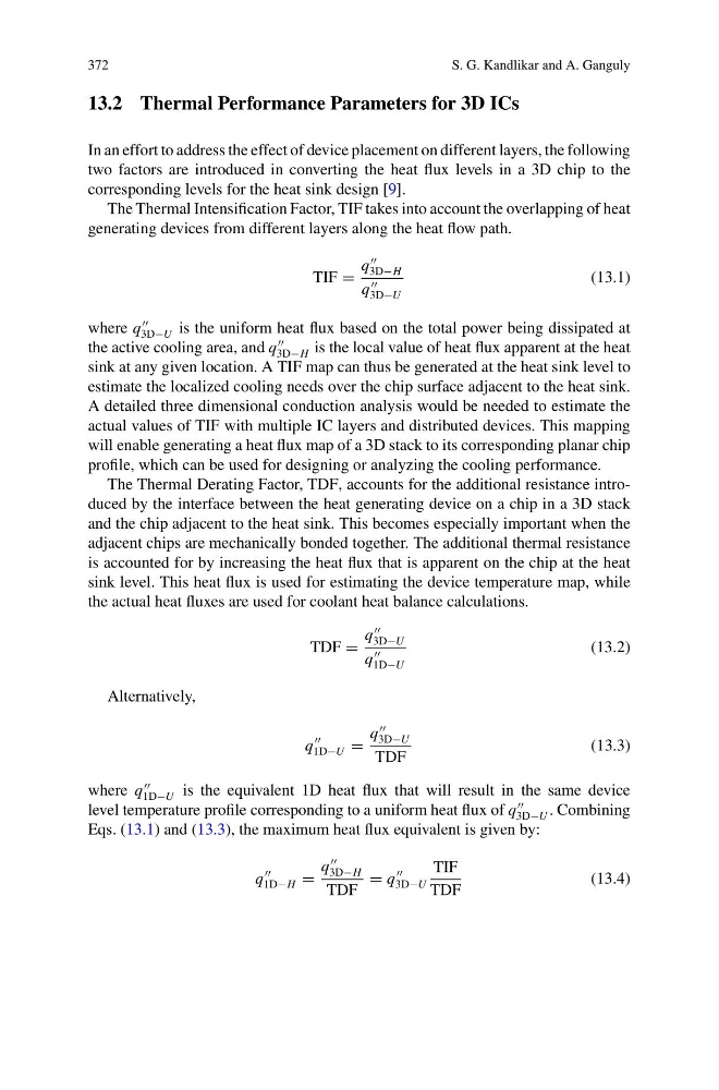
The Thermal Intensification Factor, TIF takes into account the overlapping of heat
generating devices from different layers along the heat flow path.
TIF =
q
3D−H
q
3D−U
(13.1)
where q
3D−U is the uniform heat flux based on the total power being dissipated at
the active cooling area, and q
3D−H is the local value of heat flux apparent at the heat
sink at any given location. A TIF map can thus be generated at the heat sink level to
estimate the localized cooling needs over the chip surface adjacent to the heat sink.
A detailed three dimensional conduction analysis would be needed to estimate the
actual values of TIF with multiple IC layers and distributed devices. This mapping
will enable generating a heat flux map of a 3D stack to its corresponding planar chip
profile, which can be used for designing or analyzing the cooling performance.
The Thermal Derating Factor, TDF, accounts for the additional resistance introduced by the interface between the heat generating device on a chip in a 3D stack
and the chip adjacent to the heat sink. This becomes especially important when the
adjacent chips are mechanically bonded together. The additional thermal resistance
is accounted for by increasing the heat flux that is apparent on the chip at the heat
sink level. This heat flux is used for estimating the device temperature map, while
the actual heat fluxes are used for coolant heat balance calculations.
TDF =
q
3D−U
q
1D−U
(13.2)
Alternatively,
q
1D−U =
q
3D−U
TDF
(13.3)
where q
1D−U is the equivalent 1D heat flux that will result in the same device
level temperature profile corresponding to a uniform heat flux of q
3D−U . Combining
Eqs. (13.1) and (13.3), the maximum heat flux equivalent is given by:
q
1D−H =
q
3D−H
TDF
= q
3D−U
TIF
TDF
(13.4)
S. G. Kandlikar and A. Ganguly
13.2 Thermal Performance Parameters for 3D ICs
In an effort to address the effect of device placement on different layers, the following
two factors are introduced in converting the heat flux levels in a 3D chip to the
corresponding levels for the heat sink design [9].
The Thermal Intensification Factor, TIF takes into account the overlapping of heat
generating devices from different layers along the heat flow path.
TIF =
q
3D−H
q
3D−U
(13.1)
where q
3D−U is the uniform heat flux based on the total power being dissipated at
the active cooling area, and q
3D−H is the local value of heat flux apparent at the heat
sink at any given location. A TIF map can thus be generated at the heat sink level to
estimate the localized cooling needs over the chip surface adjacent to the heat sink.
A detailed three dimensional conduction analysis would be needed to estimate the
actual values of TIF with multiple IC layers and distributed devices. This mapping
will enable generating a heat flux map of a 3D stack to its corresponding planar chip
profile, which can be used for designing or analyzing the cooling performance.
The Thermal Derating Factor, TDF, accounts for the additional resistance introduced by the interface between the heat generating device on a chip in a 3D stack
and the chip adjacent to the heat sink. This becomes especially important when the
adjacent chips are mechanically bonded together. The additional thermal resistance
is accounted for by increasing the heat flux that is apparent on the chip at the heat
sink level. This heat flux is used for estimating the device temperature map, while
the actual heat fluxes are used for coolant heat balance calculations.
TDF =
q
3D−U
q
1D−U
(13.2)
Alternatively,
q
1D−U =
q
3D−U
TDF
(13.3)
where q
1D−U is the equivalent 1D heat flux that will result in the same device
level temperature profile corresponding to a uniform heat flux of q
3D−U . Combining
Eqs. (13.1) and (13.3), the maximum heat flux equivalent is given by:
q
1D−H =
q
3D−H
TDF
= q
3D−U
TIF
TDF
(13.4)