

10 Fundamentals of Bonding Technology and Process Materials …
287
10.3.4 Epoxy Flux (No-Flow Underfill or Non-conductive
Paste)
Epoxy flux is also referred to as no-flow underfill or non-conductive paste. These
materials allow the TCB technology to complete the microbumped solder reflow
and encapsulation in a single step. The material performs the function of both
the flux and epoxy-based underfill in the TCB process, and thus it is termed as
epoxy flux and can skip flux cleaning process. In general, the epoxy flux offers
an ideal building block for TCB by achieving process simplicity and maximizing
assembly throughput. On the other hand, the material formulation limits its application because of concerns about reliability performance and assembly yield arising
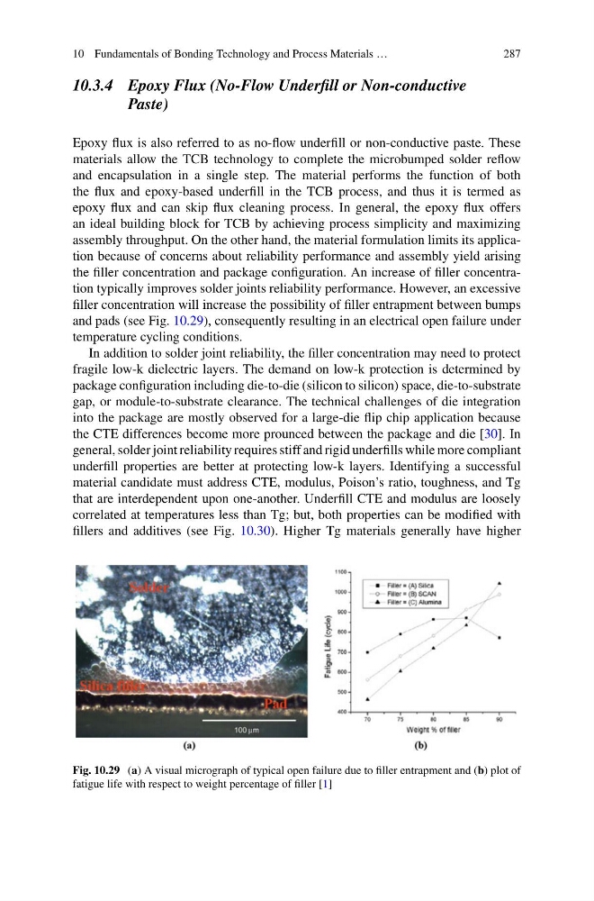
the filler concentration and package configuration. An increase of filler concentration typically improves solder joints reliability performance. However, an excessive
filler concentration will increase the possibility of filler entrapment between bumps
and pads (see Fig. 10.29), consequently resulting in an electrical open failure under
temperature cycling conditions.
In addition to solder joint reliability, the filler concentration may need to protect
fragile low-k dielectric layers. The demand on low-k protection is determined by
package configuration including die-to-die (silicon to silicon) space, die-to-substrate
gap, or module-to-substrate clearance. The technical challenges of die integration
into the package are mostly observed for a large-die flip chip application because
the CTE differences become more prounced between the package and die [30]. In
general, solder joint reliability requires stiff and rigid underfills while more compliant
underfill properties are better at protecting low-k layers. Identifying a successful
material candidate must address CTE, modulus, Poison’s ratio, toughness, and Tg
that are interdependent upon one-another. Underfill CTE and modulus are loosely
correlated at temperatures less than Tg; but, both properties can be modified with
fillers and additives (see Fig. 10.30). Higher Tg materials generally have higher
Fig. 10.29 (a) A visual micrograph of typical open failure due to filler entrapment and (b) plot of
fatigue life with respect to weight percentage of filler [1]
287
10.3.4 Epoxy Flux (No-Flow Underfill or Non-conductive
Paste)
Epoxy flux is also referred to as no-flow underfill or non-conductive paste. These
materials allow the TCB technology to complete the microbumped solder reflow
and encapsulation in a single step. The material performs the function of both
the flux and epoxy-based underfill in the TCB process, and thus it is termed as
epoxy flux and can skip flux cleaning process. In general, the epoxy flux offers
an ideal building block for TCB by achieving process simplicity and maximizing
assembly throughput. On the other hand, the material formulation limits its application because of concerns about reliability performance and assembly yield arising
the filler concentration and package configuration. An increase of filler concentration typically improves solder joints reliability performance. However, an excessive
filler concentration will increase the possibility of filler entrapment between bumps
and pads (see Fig. 10.29), consequently resulting in an electrical open failure under
temperature cycling conditions.
In addition to solder joint reliability, the filler concentration may need to protect
fragile low-k dielectric layers. The demand on low-k protection is determined by
package configuration including die-to-die (silicon to silicon) space, die-to-substrate
gap, or module-to-substrate clearance. The technical challenges of die integration
into the package are mostly observed for a large-die flip chip application because
the CTE differences become more prounced between the package and die [30]. In
general, solder joint reliability requires stiff and rigid underfills while more compliant
underfill properties are better at protecting low-k layers. Identifying a successful
material candidate must address CTE, modulus, Poison’s ratio, toughness, and Tg
that are interdependent upon one-another. Underfill CTE and modulus are loosely
correlated at temperatures less than Tg; but, both properties can be modified with
fillers and additives (see Fig. 10.30). Higher Tg materials generally have higher
Fig. 10.29 (a) A visual micrograph of typical open failure due to filler entrapment and (b) plot of
fatigue life with respect to weight percentage of filler [1]