

10 Fundamentals of Bonding Technology and Process Materials …
271
(a)
(b)
Bond head temperature
Bond force
Bond head posiƟon
1
2
3
~50˚C/s
~300˚C
100˚C/s
Thermal
expansion
1: Contact
2: Solder melting
1
2
3: Cooling
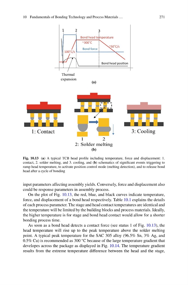
Fig. 10.13 (a) A typical TCB head profile including temperature, force and displacement: 1.
contact, 2. solder melting, and 3. cooling, and (b) schematics of significant events triggering to
ramp head temperature, to activate position control mode (melting detection), and to release bond
head after a cycle of bonding
input parameters affecting assembly yields. Conversely, force and displacement also
could be response parameters in assembly process.
On the plot of Fig. 10.13, the red, blue, and black curves indicate temperature,
force, and displacement of a bond head respectively. Table 10.1 explains the details
of each process parameter. The stage and head contact temperatures are identical and
the temperature will be limited by the building blocks and process materials. Ideally,
the higher temperature is for stage and bond head contact would allow for a shorter
bonding process time.
As soon as a bond head detects a contact force (see status 1 of Fig. 10.13), the
head temperature will rise up to the peak temperature above the solder melting
point. A typical peak temperature for the SAC 305 alloy (96.5% Sn, 3% Ag, and
0.5% Cu) is recommended as 300 °C because of the large temperature gradient that
developes across the package as displayed in Fig. 10.14. The temperature gradient
results from the extreme temperature difference between the head and the stage,
271
(a)
(b)
Bond head temperature
Bond force
Bond head posiƟon
1
2
3
~50˚C/s
~300˚C
100˚C/s
Thermal
expansion
1: Contact
2: Solder melting
1
2
3: Cooling
Fig. 10.13 (a) A typical TCB head profile including temperature, force and displacement: 1.
contact, 2. solder melting, and 3. cooling, and (b) schematics of significant events triggering to
ramp head temperature, to activate position control mode (melting detection), and to release bond
head after a cycle of bonding
input parameters affecting assembly yields. Conversely, force and displacement also
could be response parameters in assembly process.
On the plot of Fig. 10.13, the red, blue, and black curves indicate temperature,
force, and displacement of a bond head respectively. Table 10.1 explains the details
of each process parameter. The stage and head contact temperatures are identical and
the temperature will be limited by the building blocks and process materials. Ideally,
the higher temperature is for stage and bond head contact would allow for a shorter
bonding process time.
As soon as a bond head detects a contact force (see status 1 of Fig. 10.13), the
head temperature will rise up to the peak temperature above the solder melting
point. A typical peak temperature for the SAC 305 alloy (96.5% Sn, 3% Ag, and
0.5% Cu) is recommended as 300 °C because of the large temperature gradient that
developes across the package as displayed in Fig. 10.14. The temperature gradient
results from the extreme temperature difference between the head and the stage,