

214
T. Suga et al.
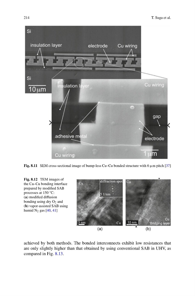
Fig. 8.11 SEM cross-sectional image of bump-less Cu–Cu bonded structure with 6 μm pitch [37]
Fig. 8.12 TEM images of
the Cu–Cu bonding interface
prepared by modified SAB
processes at 150 °C:
(a) modified diffusion
bonding using dry O 2 and
(b) vapor-assisted SAB using
humid N 2 gas [40, 41]
achieved by both methods. The bonded interconnects exhibit low resistances that
are only slightly higher than that obtained by using conventional SAB in UHV, as
compared in Fig. 8.13.
T. Suga et al.
Fig. 8.11 SEM cross-sectional image of bump-less Cu–Cu bonded structure with 6 μm pitch [37]
Fig. 8.12 TEM images of
the Cu–Cu bonding interface
prepared by modified SAB
processes at 150 °C:
(a) modified diffusion
bonding using dry O 2 and
(b) vapor-assisted SAB using
humid N 2 gas [40, 41]
achieved by both methods. The bonded interconnects exhibit low resistances that
are only slightly higher than that obtained by using conventional SAB in UHV, as
compared in Fig. 8.13.