

192
H. Ma et al.
t =
3μL
2
hγ cos θ
.
(7.26)
With scaling of package form factor, it’s important to control epoxy keep-outzone (KOZ). When epoxy is dispensed along one edge of chip, some epoxy will
enter the gap between chip and substrate, chip and chip, or chip and wafer due to
capillary flow, other epoxy will flow in the opposite direction (away from chip) due to
surface tension and wetting, increasing epoxy KOZ. Different approaches have been
adapted to reduce the opposite flow and control epoxy KOZ. From epoxy dispensing
point of view, the dispenser nozzle, seat, stroke length, and temperature, the substrate
temperature, the number of epoxy dispensing, the dispensing length, and the epoxy
weight per dispensing can be optimized; from epoxy material point of view, the
surface energy of substrate and epoxy can be fine tuned through process and material
design; from assembly process integration point of view, some barrier layer (either
physical dam or low surface energy barrier) can be applied to substrate first and
epoxy will be dispensed between these barriers and chip edge second. Due to the
height or low surface energy of these barriers, epoxy is pushed into the gap between
chip and substrate, chip and chip, and chip and wafer. In the following, Shi [103]
introduced an epoxy-dewetting model for the material selection and process control
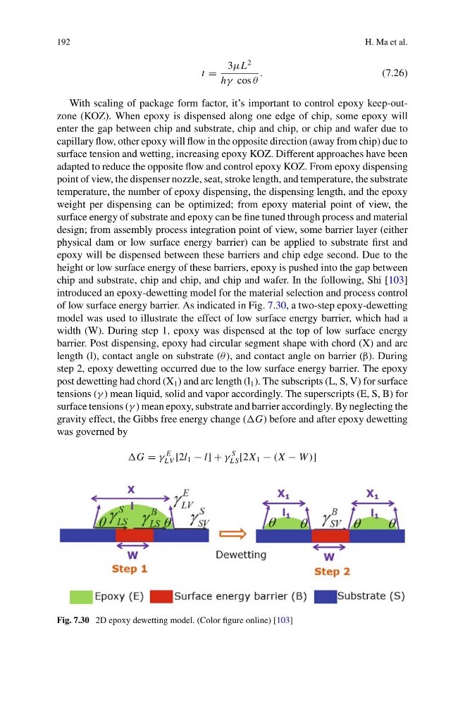
of low surface energy barrier. As indicated in Fig. 7.30, a two-step epoxy-dewetting
model was used to illustrate the effect of low surface energy barrier, which had a
width (W). During step 1, epoxy was dispensed at the top of low surface energy
barrier. Post dispensing, epoxy had circular segment shape with chord (X) and arc
length (l), contact angle on substrate (θ ), and contact angle on barrier (β). During
step 2, epoxy dewetting occurred due to the low surface energy barrier. The epoxy
post dewetting had chord (X 1 ) and arc length (l 1 ). The subscripts (L, S, V) for surface
tensions (γ ) mean liquid, solid and vapor accordingly. The superscripts (E, S, B) for
surface tensions (γ ) mean epoxy, substrate and barrier accordingly. By neglecting the
gravity effect, the Gibbs free energy change (G) before and after epoxy dewetting
was governed by
G = γ
E
LV [2l 1 − l] + γ
S
L S [2X 1 − (X − W )]
Fig. 7.30 2D epoxy dewetting model. (Color figure online) [103]
H. Ma et al.
t =
3μL
2
hγ cos θ
.
(7.26)
With scaling of package form factor, it’s important to control epoxy keep-outzone (KOZ). When epoxy is dispensed along one edge of chip, some epoxy will
enter the gap between chip and substrate, chip and chip, or chip and wafer due to
capillary flow, other epoxy will flow in the opposite direction (away from chip) due to
surface tension and wetting, increasing epoxy KOZ. Different approaches have been
adapted to reduce the opposite flow and control epoxy KOZ. From epoxy dispensing
point of view, the dispenser nozzle, seat, stroke length, and temperature, the substrate
temperature, the number of epoxy dispensing, the dispensing length, and the epoxy
weight per dispensing can be optimized; from epoxy material point of view, the
surface energy of substrate and epoxy can be fine tuned through process and material
design; from assembly process integration point of view, some barrier layer (either
physical dam or low surface energy barrier) can be applied to substrate first and
epoxy will be dispensed between these barriers and chip edge second. Due to the
height or low surface energy of these barriers, epoxy is pushed into the gap between
chip and substrate, chip and chip, and chip and wafer. In the following, Shi [103]
introduced an epoxy-dewetting model for the material selection and process control
of low surface energy barrier. As indicated in Fig. 7.30, a two-step epoxy-dewetting
model was used to illustrate the effect of low surface energy barrier, which had a
width (W). During step 1, epoxy was dispensed at the top of low surface energy
barrier. Post dispensing, epoxy had circular segment shape with chord (X) and arc
length (l), contact angle on substrate (θ ), and contact angle on barrier (β). During
step 2, epoxy dewetting occurred due to the low surface energy barrier. The epoxy
post dewetting had chord (X 1 ) and arc length (l 1 ). The subscripts (L, S, V) for surface
tensions (γ ) mean liquid, solid and vapor accordingly. The superscripts (E, S, B) for
surface tensions (γ ) mean epoxy, substrate and barrier accordingly. By neglecting the
gravity effect, the Gibbs free energy change (G) before and after epoxy dewetting
was governed by
G = γ
E
LV [2l 1 − l] + γ
S
L S [2X 1 − (X − W )]
Fig. 7.30 2D epoxy dewetting model. (Color figure online) [103]