

184
H. Ma et al.
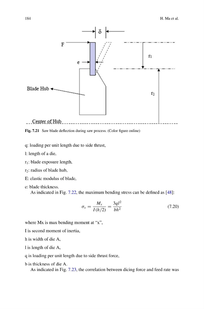
Fig. 7.21 Saw blade deflection during saw process. (Color figure online)
q: loading per unit length due to side thrust,
l: length of a die,
r 1 : blade exposure length,
r 2 : radius of blade hub,
E: elastic modulus of blade,
e: blade thickness.
As indicated in Fig. 7.22, the maximum bending stress can be defined as [48]:
σ x =
M x
I (h/2)
=
3ql
2
bh 2
(7.20)
where Mx is max bending moment at “x”,
I is second moment of inertia,
h is width of die A,
l is length of die A,
q is loading per unit length due to side thrust force,
b is thickness of die A.
As indicated in Fig. 7.23, the correlation between dicing force and feed rate was
H. Ma et al.
Fig. 7.21 Saw blade deflection during saw process. (Color figure online)
q: loading per unit length due to side thrust,
l: length of a die,
r 1 : blade exposure length,
r 2 : radius of blade hub,
E: elastic modulus of blade,
e: blade thickness.
As indicated in Fig. 7.22, the maximum bending stress can be defined as [48]:
σ x =
M x
I (h/2)
=
3ql
2
bh 2
(7.20)
where Mx is max bending moment at “x”,
I is second moment of inertia,
h is width of die A,
l is length of die A,
q is loading per unit length due to side thrust force,
b is thickness of die A.
As indicated in Fig. 7.23, the correlation between dicing force and feed rate was