

6 Atomic Scale Kinetics of TSV Protrusion
137
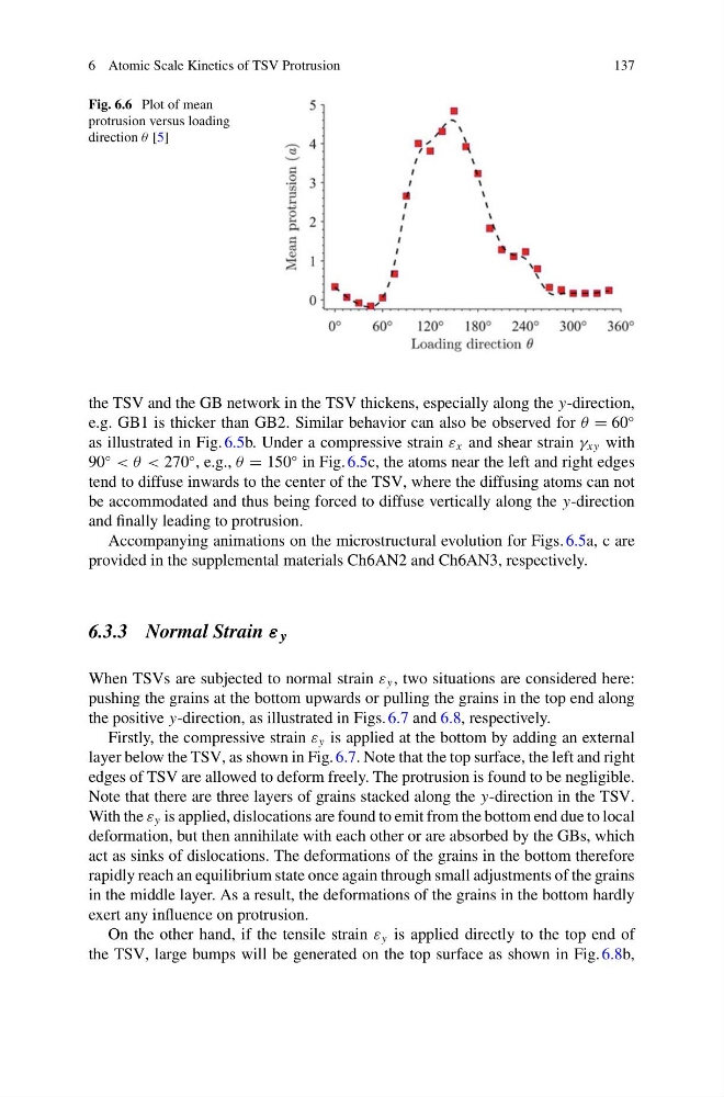
Fig. 6.6 Plot of mean
protrusion versus loading
direction θ [5]
the TSV and the GB network in the TSV thickens, especially along the y-direction,
e.g. GB1 is thicker than GB2. Similar behavior can also be observed for θ = 60
◦
as illustrated in Fig. 6.5b. Under a compressive strain ε x and shear strain γ xy with
90
◦
< θ < 270
◦ , e.g., θ = 150
◦ in Fig. 6.5c, the atoms near the left and right edges
tend to diffuse inwards to the center of the TSV, where the diffusing atoms can not
be accommodated and thus being forced to diffuse vertically along the y-direction
and finally leading to protrusion.
Accompanying animations on the microstructural evolution for Figs. 6.5a, c are
provided in the supplemental materials Ch6AN2 and Ch6AN3, respectively.
6.3.3 Normal Strain ε y
When TSVs are subjected to normal strain ε y , two situations are considered here:
pushing the grains at the bottom upwards or pulling the grains in the top end along
the positive y-direction, as illustrated in Figs. 6.7 and 6.8, respectively.
Firstly, the compressive strain ε y is applied at the bottom by adding an external
layer below the TSV, as shown in Fig. 6.7. Note that the top surface, the left and right
edges of TSV are allowed to deform freely. The protrusion is found to be negligible.
Note that there are three layers of grains stacked along the y-direction in the TSV.
With the ε y is applied, dislocations are found to emit from the bottom end due to local
deformation, but then annihilate with each other or are absorbed by the GBs, which
act as sinks of dislocations. The deformations of the grains in the bottom therefore
rapidly reach an equilibrium state once again through small adjustments of the grains
in the middle layer. As a result, the deformations of the grains in the bottom hardly
exert any influence on protrusion.
On the other hand, if the tensile strain ε y is applied directly to the top end of
the TSV, large bumps will be generated on the top surface as shown in Fig. 6.8b,
137
Fig. 6.6 Plot of mean
protrusion versus loading
direction θ [5]
the TSV and the GB network in the TSV thickens, especially along the y-direction,
e.g. GB1 is thicker than GB2. Similar behavior can also be observed for θ = 60
◦
as illustrated in Fig. 6.5b. Under a compressive strain ε x and shear strain γ xy with
90
◦
< θ < 270
◦ , e.g., θ = 150
◦ in Fig. 6.5c, the atoms near the left and right edges
tend to diffuse inwards to the center of the TSV, where the diffusing atoms can not
be accommodated and thus being forced to diffuse vertically along the y-direction
and finally leading to protrusion.
Accompanying animations on the microstructural evolution for Figs. 6.5a, c are
provided in the supplemental materials Ch6AN2 and Ch6AN3, respectively.
6.3.3 Normal Strain ε y
When TSVs are subjected to normal strain ε y , two situations are considered here:
pushing the grains at the bottom upwards or pulling the grains in the top end along
the positive y-direction, as illustrated in Figs. 6.7 and 6.8, respectively.
Firstly, the compressive strain ε y is applied at the bottom by adding an external
layer below the TSV, as shown in Fig. 6.7. Note that the top surface, the left and right
edges of TSV are allowed to deform freely. The protrusion is found to be negligible.
Note that there are three layers of grains stacked along the y-direction in the TSV.
With the ε y is applied, dislocations are found to emit from the bottom end due to local
deformation, but then annihilate with each other or are absorbed by the GBs, which
act as sinks of dislocations. The deformations of the grains in the bottom therefore
rapidly reach an equilibrium state once again through small adjustments of the grains
in the middle layer. As a result, the deformations of the grains in the bottom hardly
exert any influence on protrusion.
On the other hand, if the tensile strain ε y is applied directly to the top end of
the TSV, large bumps will be generated on the top surface as shown in Fig. 6.8b,