

7 SETI Program at the Medicina INAF Radioastronomy …
65
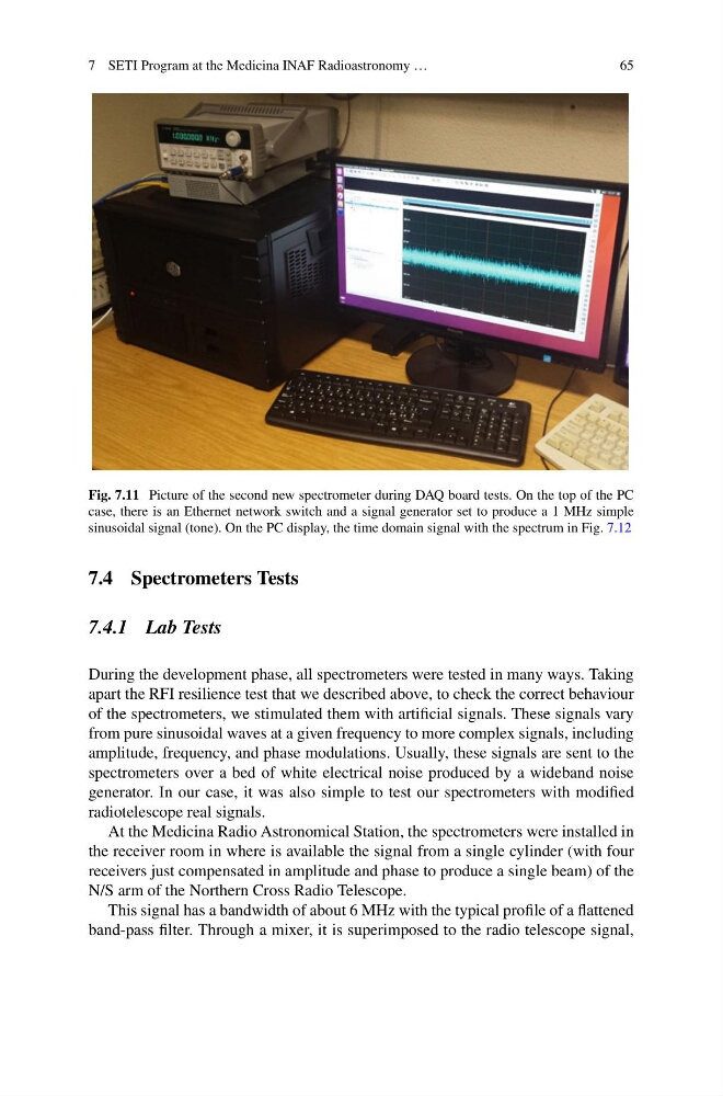
Fig. 7.11 Picture of the second new spectrometer during DAQ board tests. On the top of the PC
case, there is an Ethernet network switch and a signal generator set to produce a 1 MHz simple
sinusoidal signal (tone). On the PC display, the time domain signal with the spectrum in Fig. 7.12
7.4 Spectrometers Tests
7.4.1 Lab Tests
During the development phase, all spectrometers were tested in many ways. Taking
apart the RFI resilience test that we described above, to check the correct behaviour
of the spectrometers, we stimulated them with artificial signals. These signals vary
from pure sinusoidal waves at a given frequency to more complex signals, including
amplitude, frequency, and phase modulations. Usually, these signals are sent to the
spectrometers over a bed of white electrical noise produced by a wideband noise
generator. In our case, it was also simple to test our spectrometers with modified
radiotelescope real signals.
At the Medicina Radio Astronomical Station, the spectrometers were installed in
the receiver room in where is available the signal from a single cylinder (with four
receivers just compensated in amplitude and phase to produce a single beam) of the
N/S arm of the Northern Cross Radio Telescope.
This signal has a bandwidth of about 6 MHz with the typical profile of a flattened
band-pass filter. Through a mixer, it is superimposed to the radio telescope signal,
65
Fig. 7.11 Picture of the second new spectrometer during DAQ board tests. On the top of the PC
case, there is an Ethernet network switch and a signal generator set to produce a 1 MHz simple
sinusoidal signal (tone). On the PC display, the time domain signal with the spectrum in Fig. 7.12
7.4 Spectrometers Tests
7.4.1 Lab Tests
During the development phase, all spectrometers were tested in many ways. Taking
apart the RFI resilience test that we described above, to check the correct behaviour
of the spectrometers, we stimulated them with artificial signals. These signals vary
from pure sinusoidal waves at a given frequency to more complex signals, including
amplitude, frequency, and phase modulations. Usually, these signals are sent to the
spectrometers over a bed of white electrical noise produced by a wideband noise
generator. In our case, it was also simple to test our spectrometers with modified
radiotelescope real signals.
At the Medicina Radio Astronomical Station, the spectrometers were installed in
the receiver room in where is available the signal from a single cylinder (with four
receivers just compensated in amplitude and phase to produce a single beam) of the
N/S arm of the Northern Cross Radio Telescope.
This signal has a bandwidth of about 6 MHz with the typical profile of a flattened
band-pass filter. Through a mixer, it is superimposed to the radio telescope signal,