

58
Z. Zhao et al.
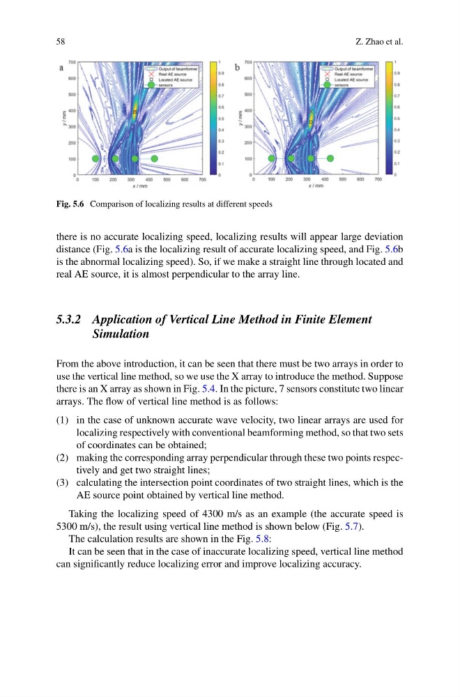
Fig. 5.6 Comparison of localizing results at different speeds
there is no accurate localizing speed, localizing results will appear large deviation
distance (Fig. 5.6a is the localizing result of accurate localizing speed, and Fig. 5.6b
is the abnormal localizing speed). So, if we make a straight line through located and
real AE source, it is almost perpendicular to the array line.
5.3.2 Application of Vertical Line Method in Finite Element
Simulation
From the above introduction, it can be seen that there must be two arrays in order to
use the vertical line method, so we use the X array to introduce the method. Suppose
there is an X array as shown in Fig. 5.4. In the picture, 7 sensors constitute two linear
arrays. The flow of vertical line method is as follows:
(1) in the case of unknown accurate wave velocity, two linear arrays are used for
localizing respectively with conventional beamforming method, so that two sets
of coordinates can be obtained;
(2) making the corresponding array perpendicular through these two points respectively and get two straight lines;
(3) calculating the intersection point coordinates of two straight lines, which is the
AE source point obtained by vertical line method.
Taking the localizing speed of 4300 m/s as an example (the accurate speed is
5300 m/s), the result using vertical line method is shown below (Fig. 5.7).
The calculation results are shown in the Fig. 5.8:
It can be seen that in the case of inaccurate localizing speed, vertical line method
can significantly reduce localizing error and improve localizing accuracy.
Z. Zhao et al.
Fig. 5.6 Comparison of localizing results at different speeds
there is no accurate localizing speed, localizing results will appear large deviation
distance (Fig. 5.6a is the localizing result of accurate localizing speed, and Fig. 5.6b
is the abnormal localizing speed). So, if we make a straight line through located and
real AE source, it is almost perpendicular to the array line.
5.3.2 Application of Vertical Line Method in Finite Element
Simulation
From the above introduction, it can be seen that there must be two arrays in order to
use the vertical line method, so we use the X array to introduce the method. Suppose
there is an X array as shown in Fig. 5.4. In the picture, 7 sensors constitute two linear
arrays. The flow of vertical line method is as follows:
(1) in the case of unknown accurate wave velocity, two linear arrays are used for
localizing respectively with conventional beamforming method, so that two sets
of coordinates can be obtained;
(2) making the corresponding array perpendicular through these two points respectively and get two straight lines;
(3) calculating the intersection point coordinates of two straight lines, which is the
AE source point obtained by vertical line method.
Taking the localizing speed of 4300 m/s as an example (the accurate speed is
5300 m/s), the result using vertical line method is shown below (Fig. 5.7).
The calculation results are shown in the Fig. 5.8:
It can be seen that in the case of inaccurate localizing speed, vertical line method
can significantly reduce localizing error and improve localizing accuracy.