

3 About an Initial Draft of a Standard Concerning Sensitivity Verification …
37
3.6 Calculating the Transmitting and Receiving
Sensitivities
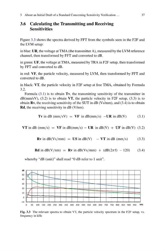
Figure 3.3 shows the spectra derived by FFT from the symbols seen in the F2F and
the LVM setup:
in blue: UR, the voltage at TMA (the transmitter A), measured by the LVM reference
channel, then transformed by FFT and converted to dB.
in green: UF, the voltage at TMA, measured by TRA in F2F setup, then transformed
by FFT and converted to dB.
in red: VF, the particle velocity, measured by LVM, then transformed by FFT and
converted to dB.
in black: VT, the particle velocity in F2F setup at free TMA, obtained by Formula
3.2.
Formula (3.1) is to obtain Tv, the transmitting sensitivity of the transmitter in
dB(mm/sV), (3.2) is to obtain VT, the particle velocity in F2F setup, (3.3) is to
obtain Rv, the receiving sensitivity of the SUT in dB (Vs/mm), and (3.4) is to obtain
Rd, the receiving sensitivity in dB (V/nm).
Tv in dB (mm/sV) = VF in dB(mm/s) −UR in dB(V)
(3.1)
VT in dB (mm/s) = VF in dB(mm/s) − UR in dB(V) + UF in dB(V) (3.2)
Rv in dB(Vs/mm) = US in dB(V) − VT in dB (mm/s)
(3.3)
Rd in dB(V/nm) = Rv in dB(Vs/mm) + (dB(2π f) − 120)
(3.4)
whereby “dB (unit)” shall read “0 dB refer to 1 unit”.
-10
0
10
20
30
40
50
60
0
50 100 150 200 250 300 350 400 450 500 550 600 650 700 750 800 850 900 950
dB
kHz
Fig. 3.3 The relevant spectra to obtain VT, the particle velocity spectrum in the F2F setup, vs.
frequency in kHz
37
3.6 Calculating the Transmitting and Receiving
Sensitivities
Figure 3.3 shows the spectra derived by FFT from the symbols seen in the F2F and
the LVM setup:
in blue: UR, the voltage at TMA (the transmitter A), measured by the LVM reference
channel, then transformed by FFT and converted to dB.
in green: UF, the voltage at TMA, measured by TRA in F2F setup, then transformed
by FFT and converted to dB.
in red: VF, the particle velocity, measured by LVM, then transformed by FFT and
converted to dB.
in black: VT, the particle velocity in F2F setup at free TMA, obtained by Formula
3.2.
Formula (3.1) is to obtain Tv, the transmitting sensitivity of the transmitter in
dB(mm/sV), (3.2) is to obtain VT, the particle velocity in F2F setup, (3.3) is to
obtain Rv, the receiving sensitivity of the SUT in dB (Vs/mm), and (3.4) is to obtain
Rd, the receiving sensitivity in dB (V/nm).
Tv in dB (mm/sV) = VF in dB(mm/s) −UR in dB(V)
(3.1)
VT in dB (mm/s) = VF in dB(mm/s) − UR in dB(V) + UF in dB(V) (3.2)
Rv in dB(Vs/mm) = US in dB(V) − VT in dB (mm/s)
(3.3)
Rd in dB(V/nm) = Rv in dB(Vs/mm) + (dB(2π f) − 120)
(3.4)
whereby “dB (unit)” shall read “0 dB refer to 1 unit”.
-10
0
10
20
30
40
50
60
0
50 100 150 200 250 300 350 400 450 500 550 600 650 700 750 800 850 900 950
dB
kHz
Fig. 3.3 The relevant spectra to obtain VT, the particle velocity spectrum in the F2F setup, vs.
frequency in kHz