

552
S. Grigg et al.
strain is currently being added to the system; however, it was not in place during the
testing presented. The second main reason for using the LabVIEW system is that
it enables further processing to be performed live, such as waveform classification
and filtering. This live processing and user feedback is vital so that the system can
inform the operator to stop tightening the screw, if a stop criteria can be developed.
AE was acquired using a Mistras Pico piezoelectric sensor bonded to the shaft of
the screwdriver using superglue. A Mistras 2/4/6 preamplifier with a built in 20 kHz–
1200 kHz analogue filter and external power source was used to amplify the signal,
with gain set to 40 dB. Data was recorded on a ‘hit’ basis, i.e. when a threshold is
crossed a certain quantity of data is recorded as well as a pre-trigger. For this testing
a threshold of 0.1 V (60 dB) was used and 2 ms of data recorded of which 400 µs
was pre-trigger. After each hit a timeout period of 3 ms was put in place. The signal
was sampled at 2 MHz.
49.3 Test Methods
Two different screws were tested for this work; a Synthes standard AO large fragment
set and a small fragment set. The large fragment set consisted of a screw with a 3.2 mm
inner core and 6.5 mm outer thread diameter. For this a 3.2 mm hole was drilled and
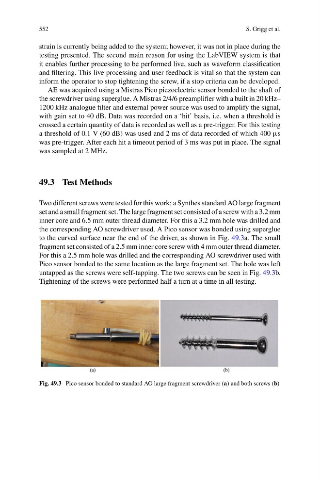
the corresponding AO screwdriver used. A Pico sensor was bonded using superglue
to the curved surface near the end of the driver, as shown in Fig. 49.3a. The small
fragment set consisted of a 2.5 mm inner core screw with 4 mm outer thread diameter.
For this a 2.5 mm hole was drilled and the corresponding AO screwdriver used with
Pico sensor bonded to the same location as the large fragment set. The hole was left
untapped as the screws were self-tapping. The two screws can be seen in Fig. 49.3b.
Tightening of the screws were performed half a turn at a time in all testing.
Fig. 49.3 Pico sensor bonded to standard AO large fragment screwdriver (a) and both screws (b)
S. Grigg et al.
strain is currently being added to the system; however, it was not in place during the
testing presented. The second main reason for using the LabVIEW system is that
it enables further processing to be performed live, such as waveform classification
and filtering. This live processing and user feedback is vital so that the system can
inform the operator to stop tightening the screw, if a stop criteria can be developed.
AE was acquired using a Mistras Pico piezoelectric sensor bonded to the shaft of
the screwdriver using superglue. A Mistras 2/4/6 preamplifier with a built in 20 kHz–
1200 kHz analogue filter and external power source was used to amplify the signal,
with gain set to 40 dB. Data was recorded on a ‘hit’ basis, i.e. when a threshold is
crossed a certain quantity of data is recorded as well as a pre-trigger. For this testing
a threshold of 0.1 V (60 dB) was used and 2 ms of data recorded of which 400 µs
was pre-trigger. After each hit a timeout period of 3 ms was put in place. The signal
was sampled at 2 MHz.
49.3 Test Methods
Two different screws were tested for this work; a Synthes standard AO large fragment
set and a small fragment set. The large fragment set consisted of a screw with a 3.2 mm
inner core and 6.5 mm outer thread diameter. For this a 3.2 mm hole was drilled and
the corresponding AO screwdriver used. A Pico sensor was bonded using superglue
to the curved surface near the end of the driver, as shown in Fig. 49.3a. The small
fragment set consisted of a 2.5 mm inner core screw with 4 mm outer thread diameter.
For this a 2.5 mm hole was drilled and the corresponding AO screwdriver used with
Pico sensor bonded to the same location as the large fragment set. The hole was left
untapped as the screws were self-tapping. The two screws can be seen in Fig. 49.3b.
Tightening of the screws were performed half a turn at a time in all testing.
Fig. 49.3 Pico sensor bonded to standard AO large fragment screwdriver (a) and both screws (b)