

46 Bearing Fault Diagnosis Using Grad-CAM …
531
The mean of p
c
k indicates a ‘importance’ weight of kth filter for class, c.
46.3 Experimental Setup and Data Acquisition
In order to validate the method, a bearing fault simulator is used for measuring healthy
and faulty-state AE signals of the bearing. The established bearing fault simulator is
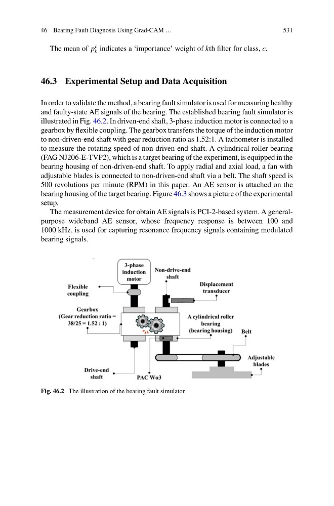
illustrated in Fig. 46.2. In driven-end shaft, 3-phase induction motor is connected to a
gearbox by flexible coupling. The gearbox transfers the torque of the induction motor
to non-driven-end shaft with gear reduction ratio as 1.52:1. A tachometer is installed
to measure the rotating speed of non-driven-end shaft. A cylindrical roller bearing
(FAG NJ206-E-TVP2), which is a target bearing of the experiment, is equipped in the
bearing housing of non-driven-end shaft. To apply radial and axial load, a fan with
adjustable blades is connected to non-driven-end shaft via a belt. The shaft speed is
500 revolutions per minute (RPM) in this paper. An AE sensor is attached on the
bearing housing of the target bearing. Figure 46.3 shows a picture of the experimental
setup.
The measurement device for obtain AE signals is PCI-2-based system. A generalpurpose wideband AE sensor, whose frequency response is between 100 and
1000 kHz, is used for capturing resonance frequency signals containing modulated
bearing signals.
Fig. 46.2 The illustration of the bearing fault simulator
531
The mean of p
c
k indicates a ‘importance’ weight of kth filter for class, c.
46.3 Experimental Setup and Data Acquisition
In order to validate the method, a bearing fault simulator is used for measuring healthy
and faulty-state AE signals of the bearing. The established bearing fault simulator is
illustrated in Fig. 46.2. In driven-end shaft, 3-phase induction motor is connected to a
gearbox by flexible coupling. The gearbox transfers the torque of the induction motor
to non-driven-end shaft with gear reduction ratio as 1.52:1. A tachometer is installed
to measure the rotating speed of non-driven-end shaft. A cylindrical roller bearing
(FAG NJ206-E-TVP2), which is a target bearing of the experiment, is equipped in the
bearing housing of non-driven-end shaft. To apply radial and axial load, a fan with
adjustable blades is connected to non-driven-end shaft via a belt. The shaft speed is
500 revolutions per minute (RPM) in this paper. An AE sensor is attached on the
bearing housing of the target bearing. Figure 46.3 shows a picture of the experimental
setup.
The measurement device for obtain AE signals is PCI-2-based system. A generalpurpose wideband AE sensor, whose frequency response is between 100 and
1000 kHz, is used for capturing resonance frequency signals containing modulated
bearing signals.
Fig. 46.2 The illustration of the bearing fault simulator